
Owners Manual
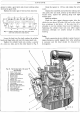

ENGINE
D/13
2
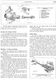
The final position
of
the
guide
is
shown in Fig.
15.
Jt must stand ft-in. (17. 0656 mm.) above the valve
spring recess in the cylinder head.
Renewing Valve Spring in Position
In
an emergency a new· valve spring can be fitted
without lifting the cylinder head,
but
it is first advisable
to bring the piston to top dead centre, thus preventing
the valve falling into the cylinder.
Remove the sparking plug, and by means
of
a screw-
driver
or
similar tool,
the
valve can be held
on
its seat
whilst the spring
is
compressed. The valve rocker shaft
can
be used as a fulcrum point by an operator using
two screwdrivers to bear on the valve spring cup each
side
of
the valve stem while the cotters are dealt with.
Distributor. To Remove and Replace .
Remove the distributor cover by releasing the two
spring clips, then disconnect the low tension wire
and
the plug leads.
Disconnect the vacuum control suction pipe
and
slacken
the
pinch bolt
of
the distributor clamping plate.
Lift
out
the
distributor.
Under
normal circumstances it will
not
be necessary
to remove the main driving spindle. Should the occasion
arise-such
as a major overhaul when the camshaft has
to
be
removed-simply
remove the clamping plate by
releasing two setpins
and
the distributor housing by
releasing one setpin. Insert a length
of
screwed
/s-in.
(7. 9375 mm.) diameter rod in the end
of
the spindle.
Withdraw the spindle
at
the same time giving the rod
a turning movement to ease removal.
On
replacement the engine must be turned until No.
1 piston
is
at
T.D.C. on
the
compression stroke, i.e.,
Nos. 7 and 8 valves
"rocking".
With the screwed
rod
still in the distributor
spindle, insert the spindle
in
the crankcase so
that
the
eccentric slot takes up a position
of
approximately
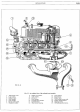
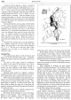
Fig. 16.
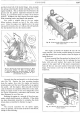
An
exploded
view
of
the distri-
butor drive.
1.
Vacuum
control
union.
2.
Distributor.
3.
Clamp
plate.
4.
Clamp
plate setpin.
5.
Bolt
for
clamp
plate.
6.
Distributor
housing.
7.
Driving
dog.
8.
Main
drive spindle.
9.
Setpin
for
housing.
10. Spindle
end.
8
H40. 293. B.
twenty past ten, the larger
portion
of
the spindle
flange being top right.
The key
of
the distributor drive coincides with the
slot
of
the spindle thus ensuring
that
the distributor
cannot be incorrectly refitted.
Ignition Timing
The correct setting for the Saloon,
Coupe
and
Commercials, using standard fuel, is 7deg. before T.D.C.
(H
in. on flywheel periphery) and, for premier fuel,
10
deg. before T.D.C.
(H
in. on flywheel periphery).
For
the Sports, using standard fuel, the setting is 2
de
g.
before
T.D.C. (
i!r
in. on flywheel periphery) and, for premier
fuel, 7 deg. before T.D.C.
(H
in. on flywheel periphery).
If
the gearbox
is
removed obtain T.D.C. for No. 1
piston on compression stroke (Nos. 7
and
8 valves
"rocking") by turning the engine with the starting handle
until the
"1
/4"
mark
on
the
flywheel
is
vertical. Make a
corresponding
mark
on
the engine backplate, also
mark
off on the flywheel the desired setting (already given)
for the fuel to be used.
Now
rotate the flywheel with
the starting handle until
on
the second revolution the
new setting
mark
coincides with the
mark
on
the engine
backplate.
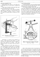
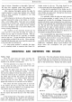
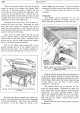
Fig. 17. Showing the
method
of
removing
the
distri-
butor
driving spindle.
1.
Screwed rod.
2.
Driving spindle.