
Owners Manual
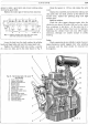

ENGINE
D/17
and
the bottom bolt
of
the starter flange. Also uncouple
the spring connecting the clutch operating lever to the
engine backplate. The car should now be lowered to the
ground and the gearbox supported beneath the bell-
housing, in a convenient manner, to keep it in its natural
position. Withdraw the four setpins from each engine
front mounting bracket
and
chassis side member.
Now attach a suitable sling to the two engine
lifting brackets, situated on top
of
the valve rocker
cover. Raise the engine very slightly and
at
the same
time pull it forward as far as it
will
go; this
will
partially
free the flywheel from the first motion shaft.
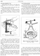
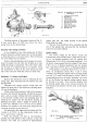
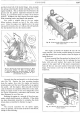
Fig. 21. Showing the engine front mounting. A. Bolts
to mounting bracket.
B.
Bolts to chassis frame.
C.
Bolts to engine front mounting plate. D. Bolt to
crankcase. E. Clearance
to
be a minimum
of
-.\-in.
and
maximum
of
-fu-in.
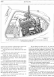
Uncouple the sling and attach
it
to the front bracket
only (Fig. 20). Remove the front mounting brackets
from the engine, then raise the engine and gearbox
simultaneously until the top
of
the gearbox is up against
the scuttle. Lift the engine a little and pull
it
forward
until the flywheel is completely off the first motion shaft.
Swing the engine round so
that
it
lies diagonally across
the engine compartment, carburetter side forward, and
then manreuvre
it
out
of
the car.
Refitting the engine is a reversal
of
the above pro-
cedure which should present
no
difficulty.
If
the clutch
has been dismantled, remember to centralise the clutch
driven plate as described in Section E, page
5.
Sports
The removal operations for the Sports engine,
minus the gearbox, are the same as those for the Saloon,
except for the following.
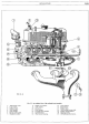
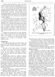
Fig. 22. Illustrating the lifting brackets on top
of
the
valve rocker cover.
The engine oil should be drained off and the oil
sump removed. This avoids possible damage by contact
with the chassis front cross member when the engine is
being lifted out.
It
is
not
essential that
the
gearbox be drained
of
oil.
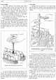
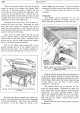
Now remove the bonnet
top
by undoing the two
bolts, with nuts
and
washers
that
secure the bonnet
support to the upper
half
of
the heater compartment.
Take off the two nuts
and
washers from each bonnet
hinge. The bonnet
is
now free to be lifted clear
of
the
bodywork.
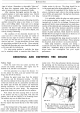
Fig. 23. Showing the securing points
of
the Sports
bonnet support.