
Owners Manual


AUSTIN
A40
SERVICE
MANUAL
E/1
CLUTCH
GENERAL DATA
Make
Type
Outside Diameter
Total Frictional Area
Thrust Bearing Type
Number of
Springs
Borg and Beck
Single
Dry
Plate-Spring
Drive
...
7i-in.(I8.4cm.)
20.03x2
sq. in.
(129.2x2
cm.
2
)
Carbon
6
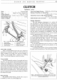
Fig. 1. The clutch pedal assembly, right-hand.
I. Clutch pedal.
5.
Clutch adjusting rod.
2.
Shaft oil nipple.
6.
Lock nut.
3.
Trunnion pin for lever.
7.
Pedal bracket spindle.
4.
Return spring.
8.
Spindle oil nipple.
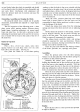
Driven Plate Assembly
This is
of
the flexible centre type
(5)
in which the
splined hub
is
indirectly attached to a disc (see Fig. 3),
which transmits the power and over-run through a
number
of
coil springs held in position by retaining
wires. Two friction linings are riveted to the disc.
Cover Assembly
The cover assembly consists
of
a pressed steel cover
(2)
and
a cast iron pressure plate
(4)
loaded by six thrust
springs (12). Mounted on the pressure plate are three
release levers
(9)
which pivot
on
floating pins
(11)
retained
by eye bolts
(10). Adjustment nuts (13) are screwed on to
the eye bolts and secured by staking.
Struts
(6)
are inter·
posed between the lugs
on
the pressure plate
and
the
outer ends
of
the release levers. Anti-rattle springs (8)
load the release levers and retainer springs
(7)
connect
the release lever plate.
Release Bearing
The graphite release bearing, shrunk into a cup (1)
is
located by a fork (15),
and
springs (14).
Total Axial Spring Pressure 780-840 lbs. (354-381 kg.)
Distance, Thrust Race to Thrust Plate
s~-§-in.
(2. 38-3.
17
mm.)
Thrust Plate Travel to Fully Released Position
.32-.37-in. (.81-.93 mm.)
Pedal Clearance (free movement) ...
!-in. (19.
05
mm.)
Running Adjustments
The only necessary adjustment is to restore the
free movement
of
the clutch pedal (i.e. movement
of
the pedal before the release bearing comes into contact
with the release lever plate
and
commences to withdraw
the clutch). As the driven plate linings wear, the free
movement
of
the pedal will gradually decrease, thus
tending to prevent the clutch fully engaging and
permit-
ting
too
great a movement
on
withdrawal. This free
movement must be maintained
at
the correct amount,
which
is
approximately !-in. (19. 05 mm.).
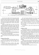
Adjustment is made by altering the effective length
of
the rod between pedal
and
clutch operating lever or
the clutch shaft
end
(see Figs. I and
4).
To
increase
the movement first slacken the locknut and screw
out
the adjusting rod by means
of
its hexagon head. Finally
tighten the locknut.
In
all cases adjustment must be such as to allow
this free movement
to
be felt by the pressure
of
one
finger on the clutch pedal.
To ascertain the
amount
of
free movement, depress
the pedal until the resistance
of
the clutch springs is felt.
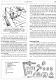
Fig,
2.
The universal drive assembly between the clutch
pedal linkage (left-hand) and the dumb-bell operating shaft
shown in exploded form.