
Owners Manual


CLUTCH
E/3
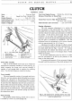
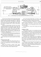
Fig. 4. The clutch pedal assembly, left-hand.
A. Spring loaded link.
B.
Adjustment rod. C.
Ad-
justment fork. D. and G. Dumb-bell universal joint
lubricators. E. Brake pedal shaft lubricator. F. Clutch
pedal shaft lubricator.
The !-in. (19.
05
mm.)
of
free movement in the
pedal will give a minimum clearance
of
lri-in.
(2.
38-
3.17 mm.) between the graphite release bearing and the
release lever plate, thus preventing continual rubbing
of
the release bearing on the plate.
For
left-hand models the pedal is separate from the
actual operating linkage although adjustment is carried
out
as
described for the right-hand mechanism. The pedal
is
anchored to its individual shaft by a cycle type cotter
and nut, whilst its shaft, which passes through two zinc
bushes housed in a bearing tube through the chassis side
member, is secured on the inside
of
the chassis by a
circlip.
One lubricating nipple is provided on the inner
end
of
the shaft.
A clutch adjusting rod takes the movement forward
to the spring loaded link arm which fits over the flats
of
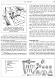
Fig. 5.
Parts
of clutch assembly tool.
A. Centre pillar.
B.
Height finger.
C. Actuating mechanism.
D.
Setpins.
E. Speedbrace.
1.
2.
Spacing washers.
3.
4.
5.
6.
Distance pieces.
7.
8.
the short shaft passing through the chassis side member.
A
nut
finally secures the arm to its shaft. The shaft
and bearing tube is identical in design to the pedal shaft
inasmuch that it has two zinc bushes, but on the inside
face the tube has a female squared universal joint
incorporating internally a thrust core.
One lubricating
nipple is screwed into this joint.
A similar joint is welded to the clutch operating
shaft
of
the bell housing,
but
instead
of
the internal cone
it
has a recess
to
take a coil spring. Then between the
clutch shaft and the linkage joint there is a dumb-bell
bar, the male squares
of
which (at each end) locate into
each universal joint, when the spring will keep the
thrust against the cone
of
the linkage joint.
To dismantle the mechanism, the dumb-bell
is
pushed inwards against the tension
of
the operating
shaft spring when the other end will be free
of
the link-
age. Pull the dumb-bell rearward clear
of
the operating
shaft.
To dismantle the linkage the outer
nut
must be
removed, the link arm withdrawn from its locating flats,
followed
by
the removal
of
the spring when the shaft
will be easily extracted from the inside
of
the chassis
side member. Thus renewal
of
zinc bushes can be readily
accomplished, theirs being a press
fit
in the bearing tube.
Removing the Clutch
To gain access
to
the clutch
it
is first necessary to
remove the complete gearbox from the engine (see
Section F/1). Before the gearbox is dismantled from the
engine, support the engine
at
its after end
by
packing
up with suitable wooden blocks or a jack.
Once the gearbox is free, slacken the clutch cover
securing screws a turn
at
a time
by
diagonal selection
until the spring pressure is relieved. Then remove the
screws completely and lift the clutch assembly away from
the flywheel. Finally remove the driven plate assembly.
Note: The clutch release lever adjustments are correctly