
Owners Manual


E/4
CLUTCH
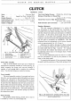
set and locked when the clutch is assembled and should
not be altered unless the clutch has been dismantled and
new parts fitted. Interference with adjustment will
throw the pressure plate out
of
position and cause the
clutch to judder.
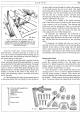
Dismantling, Assembling and Gauging the Clutch
By
using the clutch tool, a clutch can be quickly
dismantled, reassembled and adjusted to a high degree
of
accuracy.
The tool comprises
of
the following parts: a base
plate, centre pillar, spacing washers, distance pieces,
height finger, actuating mechanism, set screws, speed
brace and metal box. As this tool is universal a chart
indicating the particular parts to be used for the various
sizes
of
clutch will be found in the inside
of
the lid of
the metal box.
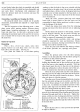
Method
of
Operation
Dismantling
With a 7!-in. (18.415 em.) clutch, select three
spacing washers
(2)
and place them over the code
letter
(B)
on the base plate. (See Fig.
6.)
Now place the clutch on to the three spacing
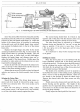
H26. 216. A.
Fig. 6. Clutch assembly tool. 18G 99.
1.
Height finger.
7.
Thrust springs.
2.
Distance piece. 8. Spacing washers.
3.
Centre pillar.
9.
Base plate.
4.
Clutch cover.
10.
Locknuts.
5.
Setpins.
11.
Eye bolts.
6.
Pressure plate. 12. Release levers.
Inset shows the clutch actuating mechanism
in
use.
washers
so
that the holes in the cover coincide with the
tapped holes in the plate, insert the set screws provided,
and tighten them, a little at a time, by diagonal selections
until the cover is firmly attached to the base plate
at
all
possible points. This
is
most important
if
the best results
are to be achieved.
Mark the cover, pressure plate lugs and release
levers with a centre punch
so
that the parts can be
reassembled in their relative positions in order to main-
tain the balance
of
the clutch.
Detach the release lever plate from the retaining
springs and remove the three eye-bolt nuts or adjusting
nuts.
Slowly release the pressure on the springs, unscrew-
ing by diagonal selection the set screws securing the
cover to the base plate. The clutch cover can then be
lifted to expose all components for inspection.
The release levers, eye-bolts, struts and springs
should be examined for wear and distortion. Renew
these parts
as
necessary, bearing in mind that the thrust
springs must only be renewed in sets.
Clean all parts and lubricate the bearing surfaces
of
the levers, eye-bolts, etc., sparingly with grease.
Assembling
Place the pressure plate over the three spacing
washers on the base plate (9), with the thrust springs
(7)
in position on the pressure plate
(6).
Assemble the release lever, eye-bolt and pin,
holding the threaded end
of
the eye-bolt and the inner
end
of
the lever as close together
as
possible. With
th~
other hand, insert the strut
in
the slots on the pressure
plate lug sufficiently to allow the plain end
of
the eye-
bolt to be inserted into the hole in the pressure plate.
Move the strut upward into the slot in the pressure
plate lug and over the ridge on the short end
of
the lever
and drop
it
into the groove formed in the latter.
Fit
the
other two levers in a similar manner.
Place the cover (
4)
over the assembled parts, ensuring
that the anti-rattle springs are in position, and that the
tops
of
the thrust springs
(7)
are directly under the seat
in the cover.
In
addition the machined portions
of
the
pressure plate lugs must be directly under the slots in
the cover through which they have to pass.
Compress the pressure springs by screwing down the
cover (
4)
to the base plate
(9)
by using the special set screws
(5)
placed through each hole in the cover. Tighten the
screws, a little
at
a time, by diagonal selection to prevent
distortion
of
the cover. The eye-bolts
(11)
and pressure
plate lugs must be guided through the holes in the cover
at
the same time.
Gauging
Screw the nuts
(10)
on to the eye-bolts and proceed
to adjust
as
follows:-