
Owners Manual


CLUTCH
E/5
%T
~WEAR
IN
POSITION
r
~~f~l~!'riALENGAGED
PoSiTiON
-.,;:_RELEASE
POSITION
.
~--~------1
2~6MAX
2%+oR-Jsz
L-------~~~~
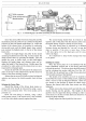
Fig. 7. A sectional diagram of the clutch unit showing the main dimensions for assembly.
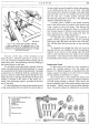
Screw the centre pillar (3) into
the
base plate
and
slip
the distance piece (2), (code 5 for 7
i"
clutch) over the pillar
followed by the cam-shaped height finger (1). Adjust the
height
of
the release levers by screwing
or
unscrewing
the eye-bolt nuts
until
the
height finger, when rotated,
just contacts
the
highest
point
on
the tip
of
the release
levers (12).
Replace
the
height finger
and
pillar by the clutch
actuating mechanism (see inset Fig.
6)
and
actuate the
clutch several times by operating the handle. This will
enable
the
parts
to
settle down
on
their knife-edges.
Replace
the
height finger
and
distance piece
and
re-
adjust
the
height
of
the
release levers. Finally repeat the
procedure
to
make quite sure the release levers are seat-
ing properly
and
gauge again.
Secure the eye-bolt nuts
(10)
and
fit the release lever
plate
on
the
tips
of
the
release levers (12) then secure
by
means
of
the
three retaining springs.
Release
the
set screws (5), a little
at
a time, by diagonal
selection and remove the clutch assembly from the base
plate.
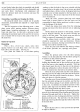
Refacing the Driven Plate
Should
the
facings
of
the driven plate require re-
newal, each rivet should
be
removed by using a
3
5
2
-in.
(3. 9687 mm.) diameter drill.
The
rivets should
not
be
punched out.
Rivet one new facing
in
position, using a blunt
ended centre punch,
if
the correct tool is not available,
to roll the rivet shanks securely against the plate.
The second facing should then be riveted
on
the
opposite side
of
the plate with the clearance holes over
the heads already formed
in
fitting the first facing.
The plate should
then
be mounted
on
a mandrel
between centres and checked for
"run
out"
as near the
edge as possible;
if
the
error
is more
than
. 0 15-in.
(.
381
mm.) press over
at
the high spots until it
is
true
within this figure.
It
is
important
to
keep friction facings free from
oil
or
grease.
Refitting the Clutch
Place the driven plate on to the flywheel with the
larger chamfered splined end
of
the driven plate
hub
towards the gearbox. The driven plate should be central-
ised by a dummy first motion shaft (see Tool No. GT.
39)
which fits
the
splined bore
of
the driven plate hub
and
the pilot bearing
of
the
flywheel.
The clutch cover assembly can now be secured
to
the flywheel by means
of
the
holding screws, tightening
them a
turn
at
a time by diagonal selection. There are
two dowels
in
the
flywheel
to
locate
the
clutch cover.
Remove the dummy shaft after these screws are fully
tightened.
Finally remove the dummy shaft
and
refit the with-
drawal bearing
and
the gearbox.
The
weight
of
the
gearbox must be supported during re-fitting in order to
avoid strain
on
the first
motion
shaft and distortion
of
the driven plate assembly.
Finally adjust the clutch pedal for free travel.