
User guide


1
EQ In
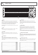
Individual bypass / enable buttons are provided for each channel. When the
button is deselected (out), the equaliser is bypassed, connecting the input
directly to the output of the device. With the EQ In button depressed, the signal
path of the equaliser is inserted between the input and output. A LED,
(A or B) indicates that the relevant equaliser channel is activated.
The bypass feature also occurs when the mains power is turned off or if power
fails to the unit.
2
Gain
Each channel of the equaliser provides input gain from - infinity to +10 dB to
ensure that unity gain can be maintained throughout your system.
3
HP Filter
Variable high pass filter adjustable from OUT (flat) up to 250 Hz to assist in
removing subsonic and other harmful lower frequencies that may damage your
speakers.
5
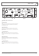
HF Contour
Applies a continuously variable shelving filter to the high frequency band
allowing subtle adjustment of the high frequency balance of a room once it is
equalised. At a frequency point of 14 kHz the contour control has an adjustment
range of ±6 dB.
4
LF Contour
Applies a continuously variable shelving filter to the low frequency band
allowing subtle adjustment of the low frequency balance of a room once it is
equalised. At a frequency point of 50 Hz the contour control has an adjustment
range of ±6 dB.
6
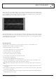
Output Meter:
Each channel of the equaliser is fitted with an accurate 8 segment LED,
RMS meter indicating level in dBu. The meters are configured to read the
output signal level of the equaliser when the EQ In button is depressed
(illuminated) and the input signal level when the EQ In button is out (channel
bypass).
Apart from identifying that a signal is present, the meter allows the operator
to use the gain control to adjust the equaliser for unity gain during set up.
7
Overload indicator (CLIP)
Identifies when the equaliser signal is being overloaded. This indicator provides
an alert when an overload occurs in either the output of the contour section,
the gain section, or the actual equaliser, providing complete monitoring of levels
through the device.
8
Frequency band faders
With 45 mm of travel and a centre detent, each of the 30 ISO faders provides
15 dB of either boost or cut to the respective frequency band of the signal
whilst maintaining a constant Q.
PAGE 6
EQ302 INSTALLATION AND OPERATION MANUAL
FRONT PANEL
21
3 2
3
5
4
5
4
contour cut HF & LFcontour boost HF & LF
6
7
8