
Manual


PAGE 4 IN600 INSTALLATION AND OPERATION MANUAL
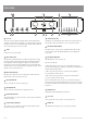
FRONT PANEL
8106 513 141 2
97
12
114 3
1
GAIN TRIM
This control is used to adjust the input gain and affects both the XLR and the
RCA inputs. The input gain can be adjusted by +/- 15dB. This allows a wide rage
of program sources to be set up with optimum gain structure. With the gain trim
in the centre position, the boost/cut is set to 0dB.
2
LEVEL
Controls the level of the input signal.
3
INPUT STATUS LEDS
Each input has an LED status indicator. The LED is green when there is signal
present and red if the signal is approaching clip. If the LED begins to light red
this would indicate the internal signal level is 6dB before clip. Note that the
front panel level control is post status LED and as such, the status LED is NOT
affected by the level control. If an input channel is clipping use the gain control to
adjust the correct amount of input level.
4
INPUT SELECTED LEDS
Each input can be switched on or off seperately via PC or RS485. This LED
indicates when the when the channel is selected.
5
AV SOURCE MASTER
This pot controls the level of the selected AV source.
6
MIC/LINE MASTER
This pot controls the overall mixed level of the Mic/Line sources.
7
MASTER VOLUME LEDS
These LED’s indicate the position of the volume control. They do not indicate the
strength of the signal.
8
SOURCE SELECT SWITCHES
These switches select the input that is routed to the audio and video outputs.
OFF will not route any source to the output.
9
SOURCE SELECT LEDS
The LED above the switch indicates when the AV source is being routed to the
audio and video outputs. OFF indicates no source is routed to the outputs.
10
PROJECTOR POWER SWITCH
This switch is used to control a projector. Pushing this button will send data
control commands out the PROJECTOR COMMS connector and trigger the
screen relays.
11
PROJECTOR POWER LED
This LED indiactes the state of the projecter.
Projector Power LED state
1. LED fl ashing means the projector has sent a command and assumes the
projector is now warming up or cooling down. If the button is pushed again while
the LED is fl ashing nothing happens.
2. LED on means the projector has been sent an ON command and the
necessary warmup period has elapsed.
3. LED off means the projector has been sent an OFF command and the
necessary cool down period has elapsed.
Projector communication is only one way so the actual state of this projector
may not match the state of the LED. If this happens, set the projector to off and
then switch of the IN600. Switch the IN600 on and now both projector and LED
should be off.
12
POWER ON LED
The AMAV logo will be illuminated when the unit is on.
13
USB Socket
This is a Type B USB connector used to connect the I600 to a PC.
14
COMMS LED
This LED indicates when data is sent or revceived via PC or RS485.