
Specifications


37
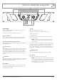
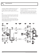
FRONT PANEL
The XA Series differ only slightly across all models and all share the same
features on their front panels.
The functions of the controls and indicators are as follows:
1
Power Switch
Press the switch to up for power on and down for power off. At start-up
(turn-on), the input to the amplifier is muted for approximately two seconds.
2
Australian Monitor Logo/On Indicator
The Australian Monitor Logo will illuminate and indicates that the amplifier is on
and receiving mains power.
3
Fault Indicator
This red LED indicates a problem with the amplifier or that it has over heated.
In the advent of a thermal overload, the internal operating temperature of one
or both amplifier channels has exceeded a safe level of operation and the
channels will be automatically muted. The fans will continue to run and once
the effected channel/s have cooled, they will unmute and return to normal
operation.
4
Attenuator
Level control for your amplifier is provided by a potentiometer on the front panel
and indicates gain. There are two controls on all XA models. Each control is
labelled for the channel which it operates.
5
VU Meter
This is a blue LED lamp which displays the level of the output stage signal.
The attack and decay time (ballistics), of the status circuit are those of a
Peak Programme Meter (P.P.M.)
6
Clip
This red LED will illuminate when clip occurs.
Clipping can occur under extreme operating conditions such as:
complex or very low loads
over driving the amplifier
It should be noted that the minimum load for the amplifier is 2 ohms per
channel (4 ohm bridged).
NOTE: The amplifier is not damaged by running into clipping, but
speakers may be. To maximise the life of your speakers, try to keep
clipping infrequent.
The clip detection circuit works by using the feedback circuit where the input
is continually compared to the output. When the input differs from the output
either due to rail clipping or current limiting the clip circuit is triggered.
This point also controls the voltage limiter so the voltage will limit at precisely
the clip point no matter what the load is or where the mains voltage level is.
7
Bridge Indicator
This amber LED will illuminate when the input switch is set to bridge.
8
Fan Grill
This is where air is drawn into the amplifier for cooling.
NOTE: You should always ensure that the fan grille is kept clean and
free from the build up of dust and lint. This will ensure longer operation
of your amplifier and reduce the possibility of it prematurely going into
thermal shutdown mode. See the section “Installation – Cooling” on page
7 for recommended cooling procedures.
1 2
6
5
8
4
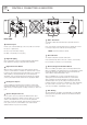
PAGE 5
XA1000 & XA1400 INSTALLATION AND OPERATION MANUAL
CONTROLS, CONNECTORS & INDICATORS