INSTALLATION AND OPERATION MANUAL AMD SERIES MIXER AMPLIFIERS AMD100 AMD200
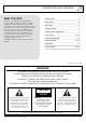
IMPORTANT SAFETY INFORMATION PRÉCAUTIONS DURANT UTILISATION 1. Read these instructions. 1. LISEZ ces instructions. 2. Keep these instructions. 2. Tenez ces instructions. 3. Heed all warnings. 3. Notez tous les avertissements. 4. Follow all instructions. 4. Suivez toutes les avertissements. 5. Do not use this apparatus near water. 5. N’utilisez pas ce produit près de l’eau (la piscine, la plage, le lac, etc.). 6. Clean only with dry cloth. 6. Nettoyez seulement avec une étoffe sèche.
INTRODUCTION AND CONTENTS AMD 100/200 INTRODUCTION 3 The AMD series of mixer amplifiers from Australian Monitor represent a quantum leap forward in connectivity, controllability & flexibility in the constant voltage amplifier market. The AMD series allows a contractor to integrate the mixer amplifier to a third party control system, enable PC control, add ICON CP control panels for remote audio control or simply use the AMD amplifiers as standard mixer amplifiers.
FRONT PANEL STEREO BGM AMD200 CHANNEL 1 CHANNEL 2 CHANNEL 3 CHANNEL 4 CHANNEL 5 CHANNEL 6 CHANNEL 7 1 CHANNEL 8 • STEREO 1 • STEREO 2 • STEREO 3 • STEREO 4 LEVEL 2 BASS TREBLE 3 MASTER 4 1 Mic/Line volume controls Used to adjust the volume of each corresponding Mic/Line Input. Front Panel volume control and the internal “Virtual” volume control are added together to give the overall total volume. For more information see page 6.
REAR PANEL 2 115VAC,50-60Hz 230VAC,50-60Hz 12 11 10 9 8 7 6 1 Mic/Line inputs Balanced mic/line input connector on a 3.81 mm pluggable connector. 2 Mic/Line Dip Switches The dip switches allow you to adjust the sensitivity or add a pad to the corresponding input. Only one DIP switch should be high at a time. 5 4 1 3 1 7 Logic Controls Low Power Mode: When Low Power mode is connected to ground the unit will enter low power mode.
THINGS TO KNOW Virtual Volume Controls We have chosen to call some of the volume controls within the AMD series “Virtual Volume” controls. This is mainly because these control sit inside the DSP of the product but also to differentiate them from the front panel volume controls. The “Virtual Volume’s” are controlled from either the PC GUI, 3rd Party Control or the ICON Control Panel. The volume control in the PC GUI will move whenever one of the controls is gestured.
INSTALLATION & CONNECTION System Requirments In order to use the AMD100/200 software it is recomended your computer meets the following requirments: CPU: 1.4 Ghz or higher Memory: 512 MB or more Hard Disk: 30 MB or more available Display: 1024 x 768 (16 bit) or higher OS: Windows XP SP2 or later, Windows Vista, Windows 7 Other: USB Connection Installation 1 Log on to Windows using an account with administrator privileges. 2 Double click on “AMD.100.
USING THE GUI Main Screen: The Main screen of the GUI is where most volume adjustments are made. From here you have control over the master output, mic/line inputs and the BGM selector. At the base of this screen there are five set up buttons to adjust features of the AMD series mixer amplifiers. Audio Setup: The Audio Setup page allows you to adjust all the DSP functions within the AMD Series.
USING THE GUI Input Level: Each input on the AMD100/200 contains a digital trim level control, this ranges from -96 dB to +12 dB. There is also an invert button to reverse the phase on that input. Input Dynamics: Each input on the AMD100/200 contains a compressor. Threshold, Ratio, Attack, Release and Output Gain may be adjusted. All adjustments are displayed on the graph to the right of the screen. Input EQ: Each input on the AMD100/200 contains EQ.
USING THE GUI Output Delay: Each output of the AMD100/200 features delay adjustment. The adjustment is in the range of: Samples: 0 - 5952 Milliseconds: 0.00 – 124.00 Meters: 0.00 – 42.90 Feet: 0.00 – 140.76 Output Dynamics: Each output of the AMD100/200 features a compressor. Threshold, Ratio, Attack, Release and Output Gain may be adjusted. All adjustments are displayed on the graph to the right of the screen. Output Level: Each output of the AMD100/200 features an output level trim.
USING THE GUI Priority: The Priority window allows you to adjust which inputs have priority over others. There are four levels of priority in the AMD Series. Level 0 – No Priority Level 1 – Low Priority Level 2 – Medium Priority Level 3 – High Priority Level 4 – Highest Priority When two inputs share the same level of priority they will both stay active when the lower priority channels mute. The threshold at which the priority will become active is adjusted via the control at the top of the page.
USING THE GUI VOX Output: The VOX Output window allows you to adjust when the VOX Output is triggered and by what sources. The VOX Output threshold control allows you to adjust at what level the will VOX output will trigger The Vox logic is selectable as to which Mic/Line input it is triggered off. By default the Vox threshold is set to -35 db with no trigger source enabled. For more infomation about the VOX trigger output see page 5.
ICON-CP/AMD100-200 The ICON-CP can be used to control certain functions of the AMD100/200. The set up the control panel all you need to do is address the panel on SW1. Switch 1-8 represent a binary address. For example to address it to ID1 all you need to do is have number 1 on, to address it to 3 have switch 1 and 2 on. 1. BGM 1 SW2 C and D do not do anything, A and B adjust the LED settings of the panel. With switch A high ambient light adjustment will be turned on.
RS485 PROTOCOL Port & Protocol Information Virtual Volume Controls: The AMD100/200 has a RJ45 connector on the rear of the unit. This connector is used for the ICON-CP control panel and also for controlling the device with an external control system via RS485. To adjust the virtual volume control of the mic/line inputs, BGM source or Master. Below is the pinout of the RJ45: %PVAL:xxyy “xx” represents the parameter ID to be adjusted and “yy” is the new value.
RS485 PROTOCOL Virtual Mute Flags BGM Source Select To toggle the mute control of Mic/Line 1-8, BGM source or Master. To select a BGM source. %PFLG:xxyy %PSRC:xx “xx” represents the parameter ID to be adjusted and “yy” is the new value of the flag. “xx” represents the source you want to select.
RS485 PROTOCOL Virtual Filter Controls Power Amp Fault Indication To adjust the virtual filter control of the master Treble and bass controls. To poll the unit for its current fault status %PVAL:xxyy “xx” represents the parameter ID to be adjusted and “yy” is the new value. Parameter ID’s 0A = Bass Filter 0B = Treble Filter The value of “yy” can span between 0x00 (10 dB of cut) and 0x14 (10 dB of boost) To request the current level of a source: %PAMP=?? The AMD100/200 will respond with.
44.00 mm (1.75”) DIMENSIONS 32.00 mm (1.25”) 482.00 mm (19.0”) 465.00 mm (18.3”) STEREO BGM AMD200 CHANNEL 1 CHANNEL 2 CHANNEL 3 CHANNEL 4 CHANNEL 5 CHANNEL 6 CHANNEL 7 CHANNEL 8 • STEREO 1 • STEREO 2 • STEREO 3 • STEREO 4 LEVEL BASS TREBLE MASTER 430.00 mm (16.9”) 115VAC,50-60Hz 230VAC,50-60Hz 330.00 mm (13.
SPECIFICATIONS Specification Conditions Frequency response: Mic/Line Inputs ----->Line Level Output Mic/Line Inputs ----->Amp Output Stereo Inputs ---->Line Level Output Stereo Inputs ---->Amp Output 20-20 kHz, -3 dB 60-20 kHz, -3 dB 20-20 kHz, -3 dB 60-20 kHz, -3 dB Signal Input -2 dB below clip Signal Input -2 dB below clip Signal Input -2 dB below clip Signal Input -2 dB below clip Total Harmonic Distortion: Mic/Line Inputs ----> Line Level Output Mic/Line Inputs ----> Line Level Output Mic/Line In
SPECIFICATIONS Specification Conditions Power Output - AMD100 4 ohm 8 ohm 70 V 100 V 100 W 100 W 100 W 100 W 20 Vrms 28.28 Vrms Power Output - AMD200 4 ohm 8 ohm 70 V 100 V 200 W 200 W 200 W 200 W 28.
ENGINEERED BY AUSTRALIAN MONITOR Address: 1 Clyde Street, Silverwater, Sydney NSW 2128 Australia. Private Bag 149, Silverwater NSW 1811 ABN 78 001 345 482 Website: www.australianmonitor.com.au International enquiries email: international@australianmonitor.com.au DISTRIBUTED IN AUSTRALIA AND NEW ZEALAND BY HILLS SVL www.hillssvl.com.au NSW P: 02 9647 1411 E: nsw@hillssvl.com.au QLD P: 07 3852 1312 E: qld@hillssvl.com.au ACT P: 02 6260 4544 E: act@hillssvl.com.au WA P: 08 9204 0200 E: wa@hillssvl.com.