AMIS MP8 8 ZONE MONITOR PANEL INSTALLATION AND OPERATION MANUAL
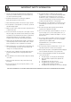
HEADING 1. IMPORTANT SAFETY INFORMATION Save the carton and packing material even if the equipment has arrived in good condition. Should you ever need to ship the unit, use only the original factory packing. 2. Read all documentation before operating your equipment. Retain all documentation for future reference. 3. Follow all instructions printed on unit chassis for proper operation. 4. Do not spill water or other liquids into or on the unit, or operate the unit while standing in liquid. 5.
INTRODUCTION AND CONTENTS The Australian Monitor Installation Series MP8 is a 2 RU monitoring panel that allows you to monitor any of up to 8, constant voltage or low impedance speaker lines. INTRODUCTION 3 FRONT PANEL 4 This can be done via the on-board 2.5” monitor speaker or via the 8 segment VU meter. The MP8 also provides signal present LED’s for each amplifier as well as LED’s to indicate which amplifier is currently selected for monitoring.
FRONT PANEL 1 1 MONITOR SPEAKER A 2.5” speaker is located behind a cloth grille. No cleaning is required. 2 MONITOR SPEAKER VOLUME CONTROL This knob controls the volume level of the monitor speaker. ☛ NOTE: The Speaker Volume Control does not affect the level of the VU indicator nor does it affect the amplifiers or speaker lines that are connected to the MP8. 3 VU METER This meter indicates the output level of the currently selected amplifier. The 0dB level is referenced to 100V.
REAR PANEL 1 3 2 1 POWER SOCKET This 2.1mm socket accepts AC or DC voltage between 12V and 24V. For DC, tip is positive. 2 24VDC IN BINDING POSTS These binding posts provide connection for 24V emergency systems and is not switched by the front panel power switch. The 24VDC IN does not provide trickle charge facility. 3 INPUT TERMINAL STRIP Paired connection from each amplifier in the system. The label AMP ‘X’ corresponds with AMPLIFIER ‘X’ on the selector switches.
INSTALLATION WIRING: Connect the speaker output of the first amplifier to INPUT terminals labelled AMP 1, maintaining correct polarity. Connect the speaker load for this amplifier to OUTPUT terminals labelled ZONE 1. ☛ A NOTE ABOUT GROUNDING: It may be necessary in some circumstances to ground the MP8 to eliminate noise from the monitor speaker.
OPERATION The SIGNAL PRESENT LED’s give a continuous indication of the signal from each of the eight connected amplifiers. Note that very low levels may not be detected. To monitor a particular amplifier, SELECT the desired amplifier. The listening level may be adjusted using the MONITOR SPEAKER VOLUME. The PROGRAM LEVEL meter gives accurate indication of signal from the selected amplifier. SETTING THE LEVEL The monitor speaker level has been designed to accept a wide range of program levels.
DIMENSIONS PAGE 8 AMIS MP8 INSTALLATION & OPERATION MANUAL
BLOCK DIAGRAM AMIS MP8 INSTALLATION & OPERATION MANUAL PAGE 9
SPECIFICATIONS 88.0 x 482.0 x 210.0 mm DIMENSIONS (h x w x d) 3.5” x 19.0” x 8.3” WEIGHT Net 4.0kg Shipping 5.4kg Net 8.8lb Shipping 11.9lb POWER INPUT: 12-24V AC/DC MONITOR VOLUME LEVELS Input for Max speaker output (10% THD) (Ref 100V) Pot @ 1: -6dB Pot @ 5: -14dB Pot @ 10: -27dB -72dB @ 1kHz -53dB @ 10kHz CROSSTALK 8VA max STANDING CURRENT (ALL VOLTAGES) DC 40mA AC 85mA MAXIMUM CURRENT METER REFERENCE -24dB (6.
AUSTRALIA AND NEW ZEALAND www.australianmonitor.com.au SYDNEY MELBOURNE BRISBANE ADELAIDE PERTH AUCKLAND (NSW & ACT SALES) (VIC & TAS SALES) (QLD SALES) (SA & NT SALES) (WA SALES) (NZ SALES) 149 Beaconsfield Street Silverwater NSW 2128 Private Bag 149 Silverwater NSW 1811 Phone: (02) 9647 1411 Fax: (02) 9648 3698 Email: nsw@audiotelex.com.au 22/277 Middleborough Road Box Hill VIC 3128 PO Box 151 Blackburn South VIC 3130 Phone: (03) 9890 7477 Fax: (03) 9890 7977 Email: vic@audiotelex.com.