PM12 & PM16 PERFORMANCE MIXING CONSOLES INSTALLATION AND OPERATION MANUAL
IMPORTANT SAFETY INFORMATION 1. Save the carton and packing material even if the equipment has arrived in good condition. Should you ever need to ship the unit, use only the original factory packing. 2. Read all documentation before operating your equipment. Retain all documentation for future reference. 3. Follow all instructions printed on unit chassis for proper operation. 4. Do not spill water or other liquids into or on the unit, or operate the unit while standing in liquid. 5.
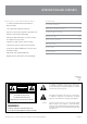
INTRODUCTION AND CONTENTS Ultra low noise 12 & 16 Channel Mic/Line Mixers INT R ODU C T ION 3 • 4 or 8 Mono Input Channels with silver plated XLRs and balanced Line Inputs U SE R GU IDE OVE R VIE W 4 • 4 Stereo Input Channels with balanced TRS Jacks MONO INPU T C HANNE L SE C T ION 5-6 • Ultra-low noise, discrete Mic Preamps with +48 V Phantom Power ST E R E O C HANNE L SE C T ION 7-8 • Balanced mic inputs for highest signal integrity • Ultra-musical 3-band EQ with mid sweep on all mono channel
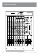
USER GUIDE OVERVIEW PAGE 4 AMPRO PM12 & PM16 INSTALLATION & OPERATION MANUAL
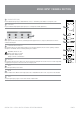
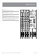
MONO INPUT CHANNEL SECTION 1 BALANCE INPUT (MIC) Electronically balanced inputs accept a standard XLR male connector. + 48V Phantom power available on each input mic socket. 2 LINE INPUT Accepts an unbalanced high impedance input signal. (Use for connecting deck, turntable, keyboard etc..) 3 3 INSERT Allows signal to be taken out from the mixer, routed through external equipment such as a compressor, and then back to the mixer to continue the final mix path.
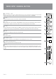
MONO INPUT CHANNEL SECTION 9 FREQUENCY + MID Mid frequency adjustment. A ‘bell response’ adjustment that allows you to select the mid frequency, variable between 250Hz and 6kHz and to then vary the response ±15dB on either side of the selected frequency, with a fixed Q of 1.5Q (bandwidth). 10 9 LOW Controls the low frequency response of each channel. Provides ±15dB at 80Hz.
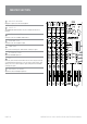
STEREO CHANNEL SECTION 18 LEFT (MONO) / RIGHT 1/4 jack input connectors. This input is half-normalised, allowing a mono signal connected to the left input to be present on both left and right output busses. 19 TRIM Adjusts the input sensitivity of each channel. 20 18 EQ ON Enables or disables the EQ. When the switch is depressed, the EQ is enabled. When the switch is in the “out” position, the EQ is disabled. 21 HIGH Controls the high frequency response of each channel. Provides ±15dB at 12kHz.
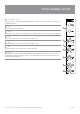
STEREO CHANNEL SECTION 25 AUX 2 This is derived after the EQ and channel fader (POST FADER, POST EQ), and follows any changers in fader level. Normally used to drive effects processing units which are fed back into the mixer and which must track the channel fader. The AUX feed is a mono sum of both left and right audio signals. 26 25 26 PAN Post fader and routes signal proportionally to the left and right outputs. 27 MUTE Press to mute the channel.
MASTER SECTION 31 TAPE IN Adjusts the level of the TAPE IN signal to the main mix. 32 AUX SENDS 1-2 Adjusts the master output level for AUX 1 and AUX 2. 33 AUX RETURN 1-2 Controls the level of the AUX return input into the main mix. 34 L-R / ALT In the up position, the return input signal is routed to the Main L-R; In the down position, the return input signal is routed to the ALT Main Out.
MASTER SECTION 35 MAIN LEVEL INDICATOR Displays the output levels of the left and right mix. 36 POWER LED The POWER LED is illuminated when AC power is available and the mixer is turned on. 37 CONTROL ROOM LEVEL Controls the level to the CONTROL ROOM monitors. 38 HEADPHONE LEVEL Controls the level of the headphone output. 39 35 PHONE JACK Stereo jack for monitoring each channel via PFL or L/R busses signal. 40 36 ALT MAIN OUT FADER 37 Adjusts the ALT MAIN output level.
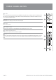
MIXER OUTPUT SECTION 45 45 46 47 43 43 TAPE INPUT 44 48 CONTROL ROOM 46 This stereo RCA input can be connected to a cassette, deck, ipod, etc. This is an alternate output, with the same signal as the headphone output. 44 47 RECORD ALT MAIN OUTPUT This stereo RCA ouput can be connected to a recording device for recording the main mix output. Outputs the same mix as main output. Level of this ouput is adjusted by the “ALT MAIN OUT” fader.
INSTALLATION PAGE 12 AMPRO PM12 & PM16 INSTALLATION & OPERATION MANUAL
SPECIFICATIONS Mono Inputs Mic Input Electronically balanced, discrete input configuration Distortion (THD & N) 0.1% at +4 dBu, 1 kHz, Bandwidth 80 kHz Mic E.I.N (22 Hz - 22 kHz) -129.5 dBu, 150 Ohm source -117.3 dBqp, 150 Ohm source -132.0 dBu, input shorted -122.
SPECIFICATIONS Master Mix section Frequency Response 20Hz ~ 20kHz. +1/-2dB Max Output +20 dBu balanced Aux Send Max Out +20 dBu unbalanced Control Room Out +20 dBu unbalanced Signal-To-Noise Ratio 90 dBu, all channels at Unity Gain Crosstalk (at 1 kHz) -70 dB between input channels; -70dB between input/output channels Power supply Mains Voltages USA/Canada U.K.
NOTES AMPRO PM12 & PM16 INSTALLATION & OPERATION MANUAL PAGE 15
AUSTRALIA AND NEW ZEALAND www.australianmonitor.com.au SYDNEY MELBOURNE BRISBANE ADELAIDE PERTH AUCKLAND (NSW & ACT SALES) (VIC & TAS SALES) (QLD SALES) (SA & NT SALES) (WA SALES) (NZ SALES) 1 Clyde Street Silverwater NSW 2128 Private Bag 149 Silverwater NSW 1811 Phone: (02) 9647 1411 Fax: (02) 9648 3698 Email: nsw@audiotelex.com.au 22/277 Middleborough Road Box Hill VIC 3128 PO Box 151 Blackburn South VIC 3130 Phone: (03) 9890 7477 Fax: (03) 9890 7977 Email: vic@audiotelex.com.