
Operating instructions

11
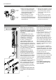
Bauliche Voraussetzungen
• Das Gerät muss dauerhaft an fest ver-
legte Leitungen angeschlossen werden.
Das Gerät muss an den Schutzleiter
angeschlossen werden.
• Die Elektroleitungen müssen sich in
einem einwandfreien Zustand befinden
und dürfen nach der Montage nicht
mehr berührbar sein.
• Installationsseitig ist eine allpolige
Trennvorrichtung mit einer Kontakt-
öffnungsweite von mindestens
3 mm pro Pol vorzusehen (z.B. über
Sicherungen).
• Zur Absicherung des Gerätes ist ein
Sicherungselement für Leitungsschutz
mit einem dem Gerätenennstrom an ge-
passten Auslösestrom zu montieren.
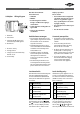
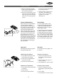
Lastabwurfrelais
Beim Anschluss weiterer Drehstromgeräte
kann ein Lastabwurfrelais für elektro-
nische Durchlauferhitzer (CLAGE Art.Nr.
82250) an den Außenleiter L
2
angeschlos-
sen werden.
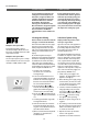
LCD Beschreibung
0
Normaler Betrieb,
Werkeinstellung
1
Betrieb mit normalem
Lastabwurfrelais
2
Betrieb mit empfindlichem
Lastabwurfrelais
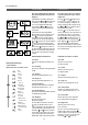
Drücken Sie zum Ändern der Betriebsart
gleichzeitig alle vier Tasten (
,
,
und
) und warten, bis der gewünschte
Wert (0, 1 oder 2) im Display erscheint,
dann Tasten loslassen. Zunächst ist die
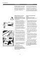
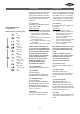
Schaltplan
Structural prerequisites
• The appliance must be installed via a
permanent connection. Heater must be
earthed!
• The electric wiring should not be
injured. After mounting, the wiring
must not be direct accessible.
• An all-pole disconnecting device (e.g.
via fuses) with a contact opening
width of at least 3 mm per pole should
be provided at the installation end.
• To protect the appliance, a fuse ele-
ment must be fitted with a tripping
current commensurate with the
nominal current of the appliance.
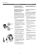
Load shedding relay
If further three-phase appliances are con-
nected, a load shedding relay designed
for electronic instantaneous water heaters
(CLAGE no. 82250)
can be connected to
phase conductor L
2
.
LCD Description
0
Normal operation,
manufacturer‘s setting
1
Operation with normal
load shedding relay
2
Operation with sensitive
load shedding relay
A special operating mode must be selec-
ted on the appli ance for this purpose.
To change the operating mode, press
the four keys (
, , and
) simul-
taneously and wait until the desired mode
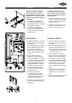
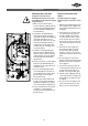
7. Elektroanschluss 7. Electrical connection
1. Elektronik
2. Heizelement
3. Sicherheitsdruckbegrenzer und
Sicherheitstemperatur begrenzer
4. Klemmleiste
1. Electronic circuitry
2. Heating element
3. Safety pressure switch and Safety
thermal cut-out
4. Terminal strip
21
4
3
Wiring diagram
Nur durch den Fachmann!
Zu beachten sind:
• VDE 0100
• EN806-2
• Bestimmungen der örtlichen
Energie- und Wasserversorgungs-
unternehmen
• Technische Daten und Angaben auf
Typenschild
• Gerät an den Schutzleiter
anschließen!
Only by a specialist!
Please observe:
• The installation must comply with
current IEC and national local regu-
lations or any particular regula-
tions, specified by the local electric-
ity supply company
• The rating plate and technical speci-
fications
• The unit must be earthed!