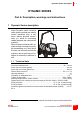
Dynamic series user manual Description, warnings and instructions Conformity and frequencies (915MHz)
The attached documentation is an integral part of the radio remote control and it aims at providing the instructions needed for using and maintaining the system, with an eye on its safety functions.
INDEX Part A: Description, warnings and instructions 1 Dynamic Series description ............................................................................... A - 1 1.1 Technical data ................................................................................................. A - 1 1.2 Applications ..................................................................................................... A - 2 1.3 Radio link .................................................................................
7 Troubleshooting ................................................................................................ A - 23 7.1 Radio remote controls with Data Feedback function .................................... A - 23 7.2 Radio remote controls with wire control ........................................................ A - 23 7.3 Solutions in case of malfunction ................................................................... A - 23 Part B: Conformity and frequencies 1 Conformity .......................
Dynamic Series description A-1 DYNAMIC SERIES Part A: Description, warnings and instructions 1 Dynamic Series description Autec Dynamic series industrial radio remote controls are used to control machines from a distance, without physical connections (i.e. wires or connecting cables) between the user and the machine.
A-2 Dynamic Series description 1.2 Applications In compliance with the risk assessment (see chapter 2), this radio remote control can be installed on hoisting and material handling machines and on machines for moving, raising and transporting people (i.e. hydraulic cranes, aerial work platforms, telehandlers, concrete pumps).
Dynamic Series description A-3 1.4 Classification of commands Commands sent by the transmitting unit are classified according to their type. 1.4.1 Command type: analogue, digital or direction command Commands sent by the transmitting unit can either be analogue or digital. Analogue commands generate proportional outputs as a function of the position of the corresponding actuator. Digital commands switch the status of their corresponding output, according to the position of the related actuator.
A-4 Dynamic Series description 1.5.2 Protection against unintended movements from the standstill position (UMFS) This safety function protects the system “machine+radio remote control” from unintended movements, namely machine movements not activated intentionally by the user, but resulting from possible electrical and mechanical failure of the radio remote control. Such safety function checks the neutral (rest) position of the actuators that control the machine's movements.
Risk assessment A-5 2 Risk assessment As required standards ISO 12100 and ISO 14212, all machines must undergo risk assessment. It is therefore necessary to evaluate, within the limits of this assessment, if the machine can be radio remote controlled. The radio remote control can only be used if this assessment gives positive results. 2.
A-6 Risk assessment The machine manufacturer and/or the person who decides upon radio remote control use and installation is responsible for this risk assessment. Autec cannot be held responsible if this assessment is not carried out correctly. If required by the risk assessment, draw up protection measures to prevent, reduce and report potential hazard situations. 2.
Warnings A-7 3 Warnings In addition to all instructions provided by the machine manufacturer, by the installer of the radio remote control and by the person responsible for the safety of the work area, users shall always respect the following warnings. 3.1 Before starting to work The transmitting unit shall be used in a simple and comfortable way, avoiding accidental falls. The harness provided with the radio remote control serves as such.
A-8 Warnings Do not touch the receiving unit’s metal parts as they may reach high, potentially dangerous temperatures. In case of malfunction, disable the system “machine+radio remote control” until the problem has been completely solved. 3.3 After using the radio remote control Switch off the transmitting unit when work is stopped or temporarily interrupted. Do not leave the load hanging (even when changing the battery). Never leave the transmitting unit unguarded when the S-KEY is inserted.
Radio remote control lifecycle A-9 4 Radio remote control lifecycle To ensure a safe and long-lasting operation of Dynamic series industrial radio remote controls, carefully follow the instructions provided for each stage of the product lifecycle. 4.1 Transportation and storage Radio remote controls must always be transported and stored inside their original packing until they are installed on the machine. Environmental transportation and storage conditions are given in the following table.
A - 10 Radio remote control lifecycle All warnings for a correct use are given in chapter 3. All instructions for a correct use are given in chapters 5 and 6. Environmental working conditions are given in the following table. Temperature Transmitting unit Receiving unit Class 5K4H -25°C to +55°C (-13°F to +130°F) Class 5K2 Relative Humidity Air Pressure Class 5K2 5% to 95% Class 5K2 70 kPa to 106 kPa -25°C to +70°Ca (-13°F to +158°F) a.
Radio remote control lifecycle A - 11 4.4.1 Routine maintenance Routine maintenance consists of operations needed to preserve the radio remote control normal usage conditions, thus implementing fine-tuning, checks, planned replacement actions that necessarily arise from the normal use of the product.
A - 12 Radio remote control lifecycle 4.4.
Radio remote control lifecycle A - 13 4.4.5 Preventive replacement of actuators (joysticks, pushbuttons and selectors) Each actuator on the transmitting units can be used for a maximum number of operations. Replace joysticks, pushbuttons and selectors on the transmitting unit before they reach the maximum number of operations, even though they are still working. Replacement prevents possible failures that may lead to loss of safety. Actuator Max. operations 5x10⁶ Actuator Max.
A - 14 Radio remote control lifecycle 4.5 Machine maintenance Follow instructions provided by the machine manufacturer and by the installer of the radio remote control, in order to carry out machine maintenance. When carrying out maintenance operations on the machine: - always remove the S-KEY from the transmitting unit - disconnect power from the receiving unit 4.6 Disposal When disposing of a radio remote control, give it to the waste separate collecting services in the user's country.
General operating instructions A - 15 5 General operating instructions 5.1 Starting up the radio remote control Starting up the radio remote control consists in building a radio link between the transmitting and the receiving unit. For this purpose, you need to: 1. power on the receiving unit respecting the voltage limits provided in the technical data. The POWER LED switches on 2. insert a charged battery in the transmitting unit (see paragraph 6.1) 3. insert the S-KEY in the transmitting unit 4.
A - 16 General operating instructions 5.3.1 Operation with display If the transmitting unit has a display, it is possible to visualise signal icons, measurements collected from the machine and their description. Information displayed and how it is displayed (icons and/or measurements and/ or descriptions) depend on the settings chosen by the machine manufacturer.
General operating instructions A - 17 5.5.1 Low battery The transmitting unit indicates if the battery is not sufficiently charged (the red LED blinks and an acoustic signal sounds). The transmitting unit automatically switches off after 3.5 minutes from the beginning of the signal. The battery shall be replaced with a charged one (see paragraph 6.1). 5.5.
A - 18 Working 6 Working 6.1 BATTERY The Dynamic series' transmitting units can only be powered through Autec rechargeable batteries. See the battery charger manual enclosed in the packaging with the battery charger for any warnings and instructions regarding the batteries. Batteries shall be inserted in their housing in the transmitting unit, with the technical data plate facing down and their contacts towards the contacts on the transmitting unit. 2 1 3 4 To insert a battery, proceed as follows: 1.
Working A - 19 As the radio remote control address is stored in the S-KEY, use it with utmost care to reduce risks that may result from incorrect handling. If the main transmitting unit cannot be used because it has been lost or damaged, the back-up transmitting unit can be used instead. In this case, insert the S-KEY in the back-up unit. The back-up unit is identical to the main unit; the only difference is the presence of the plate “BACK-UP UNIT” on the battery housing. 6.
A - 20 Working 6.5 Command meaning Commands on the transmitting unit are established according to the machine's operations and functions. They are established by the machine manufacturer, who also chooses the symbols used. Some of the commands available on the transmitting unit may be those provided below; in this case, symbols used are generally those given here: RPM+/- (during normal operation) This switch increases (rpm +) or decreases (rpm -) the engine revolutions of the remote controlled machine.
Working A - 21 ENGINE This switch is used to switch on and off the engine of the remote controlled machine. Symbol Meaning This symbol indicates that the engine is powered on. This symbol indicates that the engine is switched off.
A - 22 Working 6.7 Cable control The wire control is used: - in particular working conditions, established by the machine manufacturer - when it is not possible to build a radio link between the radio remote control units - when working in environments where using radio frequencies is not allowed or is dangerous - when a fully charged battery is not available.
Troubleshooting A - 23 7 Troubleshooting When the radio remote control does not work: - bring the transmitting unit close to the receiving unit to avoid radio interference and disturbances - establish whether the problem lies with the radio remote control or with the machine. Therefore, before any inspection, try to control the machine from a control unit different from the radio remote control, if present. If the problem persists, it lies with the machine.
A - 24 Dynamic Series Part A: Description, warnings and instructions
Conformity B-1 DYNAMIC SERIES Part B: Conformity e frequencies 1 Conformity Each of these radio remote controls complies with the following requirements: - FCC (Federal Communication Commission) Part 15 - IC (Industry Canada) RSS-102 Unit FCC ID IC number FJS OQA-FJSNF022 9061A-FJSNF022 FJL OQA-FJLNF022 9061A-FJLNF022 FJM OQA-FJMNF022 9061A-FJMNF022 CRS OQA-CRSNA022 9061A-CRSNA022 ARM OQA-ARMNB022 OQA-ARMNC022 9061A-ARMNB022 9061A-ARMNC022 ARS OQA-ARSND022 9061A-ARSND022 Operation is
B-2 Market Available radio channels with static mode .................................................................... 260 Channel spacing ....................................................................................................... 50 kHz Dynamic series industrial radio remote controls communicate either in dynamic or static mode. Mode is set by the machine manufacturer. 2.
AUTEC SRL via pomaroli, 65 Caldogno (VI) Italy - phone: +39.0444.901000 - mail: info@autecsafety.com - www.autecsafety.