Original instructions Dynamic Series User manual Description, warnings and instructions LIDYNE00-04
Warnings and caption for the documentation attached to the radio remote control The attached documentation is an integral part of the radio remote control and it aims at providing the instructions needed for using and maintaining the system, paying particular attention to the safety functions.
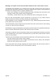
Three symbols are employed throughout documentation, which are used to highlight specific safety-related issues. They are classified according to the hazardous situation that may arise and on the possible consequences: Symbol If the highlighted instructions are not respected ... ... a dangerous situation will occur… ...consequences for people may be… ...consequences for property may be… …highly probable. … critical (death or physical damage). … critical. … probable.
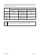
DYNAMIC SERIES Part A: Description, warnings and instructions INDEX 1 2 3 4 5 6 Radio remote control description ......................................................................... 7 1.1 How the radio remote control works .................................................................. 7 1.2 Technical Data .................................................................................................. 7 1.3 Applications ........................................................................
7 Troubleshooting ................................................................................................... 7.1 Radio remote controls with Data Feedback function ........................................ 7.2 Radio remote controls with wire control .......................................................... 7.3 Solutions in case of malfunction ......................................................................
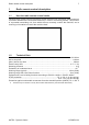
Radio remote control description 1 Radio remote control description 1.1 How the radio remote control works 7 Industrial radio remote controls are used to control machines from a distance, without physical connection between the user and the machine (i.e. wires or connecting cables). They consist of a portable transmitting unit, from which the user remotely controls the machine, and a receiving unit installed on board the machine itself. 1.2 Technical Data Command response time .....................
1.3 Radio remote control description Applications Dynamic series radio remote controls can be installed on hoisting and material handling machines and on machines for moving, raising and transporting people (e.g. hydraulic cranes, aerial work platforms, telehandlers, concrete pumps).
Radio remote control description 1.5 9 Classification of commands Commands sent by the transmitting unit are classified according to their type. 1.5.1 Command type: analogue, digital or direction command Commands sent by the transmitting unit can either be analogue or digital. Analogue commands generate proportional outputs as a function of the position of the corresponding actuator. Digital commands switch the status of their corresponding output, according to the position of the related actuator.
Radio remote control description 1.6.2 Protection against unintended movements from the standstill position (UMFS) This safety function protects the system “machine+radio remote control” from unintended movements, namely machine movements not activated intentionally by the user, but resulting from possible electrical and mechanical failure of the radio remote control. Such safety function checks the neutral (rest) position of the actuators that control the machine's movements.
Risk assessment 2 11 Risk assessment When using and installing an industrial radio remote control it is therefore always necessary to evaluate if the machine can be radio remote controlled. In fact, as required by standards ISO 12100 and ISO 14121, all machines must undergo risk assessment. The radio remote control can only be installed if this assessment gives positive results.
Risk assessment 2.1.3 Protection from unintended activation The transmitting unit housing is manufactured so that it protects the actuators from unintentional activation, while meeting at the same time the operating needs, the comfort requirements and law limits. Assessment shall be made to establish possible additional protection measures for the actuators (i.e.
Warnings for use 3 13 Warnings for use In addition to all instructions provided by the machine manufacturer, by the installer of the radio remote control and by the person responsible for the safety of the work area, users shall always respect the following warnings. 3.
Warnings for use Visually and directly follow all movements of the machine and its load and remain inside the radio remote control working range. Pay particular attention to warnings and visual and acoustic signals, and take all measurements and steps to avoid that movements of the remote controlled machine may lead to hazardous situations for people and/or property. In case of malfunction, disable the system “machine+radio remote control” until the problem has been completely solved.
Radio remote control life cycle 4 15 Radio remote control life cycle To ensure safe and long-lasting operation of industrial radio remote controls, carefully follow the instructions provided for each stage of the product life cycle. 4.1 Transportation and storage Radio remote controls must always be transported and stored inside their packing until they are installed on the machine. Environmental transportation and storage conditions are given in the following table.
4.3 Radio remote control life cycle Use The use of industrial radio remote controls is strictly limited to skilled and properly trained personnel. When the radio remote control is installed on machines on board vehicles, switch off the receiving unit while the vehicle is travelling. All warnings for correct use are given in chapter 3. All instructions for correct use are given in chapters 5 and 6. Environmental working conditions are given in the following table.
Radio remote control life cycle 17 Before any maintenance operation, remove the battery from the transmitting unit and disconnect power supply from the receiving unit. After each maintenance operation, always make sure that all commands sent by the transmitting unit only activate the corresponding expected operations. In case of malfunction or damaged parts, disable the system “machine+radio remote control” until the problem has been completely solved.
Radio remote control life cycle During normal operation: -- check structural integrity of the transmitting unit -- make sure that materials that could endanger the transmitting unit usage and safety (such as concrete, sand, lime, dust) do not deposit on it. After using the radio remote control: -- clean the transmitting unit: never use solvents or flammable/corrosive materials and do not use high-pressure water cleaners or steam cleaners -- store the transmitting unit in clean and dry areas. 4.4.
Radio remote control life cycle 19 4.4.5 Preventive replacement of actuators (joysticks, pushbuttons and selectors) Each actuator on the transmitting units can be used for a maximum number of operations. Replace joysticks, pushbuttons and selectors on the transmitting unit before they reach the maximum number of operations, even though they are still working. Replacement prevents possible failures that may lead to loss of safety. Actuator Max. operations Actuator Max.
4.5 Radio remote control life cycle Machine maintenance Follow instructions provided by the machine manufacturer and by the installer of the radio remote control, in order to carry out machine maintenance. When carrying out maintenance on the machine, always disconnect power supply from the receiving unit. Disconnect all receiving unit's electrical connections whenever machine maintenance is carried out (i.e. when soldering). 4.
General operating instructions 5 General operating instructions 5.1 Starting up the radio remote control 21 Starting up the radio remote control consists in building a radio link between the transmitting and the receiving unit. For this purpose, you need to: 1. power on the receiving unit respecting the voltage limits provided in the technical data. The POWER LED switches on 2. insert a charged battery in the transmitting unit (see paragraph 6.1) 3.
General operating instructions 5.3.1 Operation with display If the transmitting unit has a display, it is possible to visualise signal icons, measurements collected from the machine and their description. Information displayed and how it is displayed (icons and/or measurements and/or descriptions) depend on the settings chosen by the machine manufacturer.
General operating instructions 23 5.5.1 Low battery The transmitting unit indicates if the battery is not sufficiently charged (the red LED blinks and an acoustic signal sounds). The transmitting unit automatically switches off after 3.5 minutes from the beginning of the signal. The battery needs to be replaced with a charged one (see paragraph 6.1). 5.5.
Operation 6 Operation 6.1 BATTERY The Dynamic series' transmitting units can only be powered through Autec rechargeable batteries. See the battery charger manual enclosed in the packaging with the battery charger for any warnings and instructions regarding the batteries. Batteries shall be inserted in their housing in the transmitting unit, with the technical data plate facing down and their contacts towards the contacts on the transmitting unit. To insert a battery, proceed as follows: 1.
Operation 25 The S-KEY can only be used in the transmitting unit of the radio remote control where it belongs. As the radio remote control address is stored in the S-KEY, use it with utmost care to reduce risks that may result from incorrect handling. 6.2.1 BACK-UP UNIT If the transmitting unit cannot be used because it has been lost or damaged, a transmitting unit called "BACK-UP UNIT" can replace it.
6.4 Operation STOP pushbutton The STOP pushbutton should be pressed when it is necessary to immediately stop the machine when a dangerous condition occurs. When the STOP pushbutton is pressed, the machine stops (active stop: see paragraph 1.6.1), and the transmitting unit switches off. To start working again after the STOP pushbutton has been pressed: 1. make sure that the working and usage conditions are safe 2. turn the STOP pushbutton in the arrow direction to unlock it 3.
Operation 6.5 27 Command meaning Commands on the transmitting unit are established according to the machine's operations and functions. They are established by the machine manufacturer, who also chooses the symbols used. Some of the commands available on the transmitting unit may be those described in the following paragraphs; in this case, symbols used are generally those given here: 6.5.
Operation 6.5.4 ENGINE This switch is used to switch on and off the engine of the remote controlled machine. Symbol Meaning This symbol indicates that the engine is powered on. This symbol indicates that the engine is switched off. 6.5.
Operation 6.7 29 Cable control The wire control is used: -- in particular working conditions, established by the machine manufacturer -- when it is not possible to build a radio link between the radio remote control units -- when working in environments where using radio frequencies is not allowed or is dangerous -- when a fully charged battery is not available.
7 Troubleshooting Troubleshooting When the radio remote control does not work: -- bring the transmitting unit close to the receiving unit to avoid radio interference and disturbances -- establish whether the problem lies with the radio remote control or with the machine. Therefore, before any inspection, try to control the machine from a control unit different from the radio remote control, if present. If the problem persists, it lies with the machine.
AUTEC SRL via pomaroli 65 Caldogno (VI) Italy - phone: +39 0444 901000 - mail: info@autecsafety.com - www.autecsafety.