Table of Contents 1. 2. 3. 4. 5. 6. 7. 8. SAFETY PRECAUTIONS AND WARNINGS .............................................. 1 GENERAL INFORMATION .......................................................................... 2 2.1 ON-BOARD DIAGNOSTICS (OBD) II ............................................................. 2 2.2 DIAGNOSTIC TROUBLE CODES (DTCS) ........................................................ 2 2.3 LOCATION OF THE DATA LINK CONNECTOR (DLC) .................................... 3 2.
1. Safety Precautions and Warnings To prevent personal injury or damage to vehicles and/or the scan tool, read this instruction manual first and observe the following safety precautions at a minimum whenever working on a vehicle: Always perform automotive testing in a safe environment. Wear safety eye protection that meets ANSI standards. Keep clothing, hair, hands, tools, test equipment, etc. away from all moving or hot engine parts.
2. General Information 2.1 On-Board Diagnostics (OBD) II The first generation of On-Board Diagnostics (called OBD I) was developed by the California Air Resources Board (ARB) and implemented in 1988 to monitor some of the emission control components on vehicles. As technology evolved and the desire to improve the On-Board Diagnostic system increased, a new generation of On-Board Diagnostic system was developed. This second generation of On-Board Diagnostic regulations is called "OBD II".
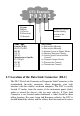
DTC Example P0202 Systems B=Body C=Chassis P=Powertrain U=Network Identifying specific malfunctioning section of the systems Code Type Generic (SAE): P0, P2, P34-P39 B0, B3 C0, C3 U0, U3. Manufacturer Specific: P1, P30-p33 B1, B2 C1, C2 U1, U2 Sub-systems 1= Fuel and Air Metering 2= Fuel and Air Metering 3= Ignition System or Engine Misfire 4= Auxiliary Emission Controls 5= Vehicle Speed Control and Idle Controls 6= Computer Output Circuits 7= Transmission Controls 8= Transmission Controls 2.
the connector. If the DLC cannot be found, refer to the vehicle‟s service manual for the location. 2.4 OBD II Readiness Monitors An important part of a vehicle‟s OBD II system is the Readiness Monitors, which are indicators used to find out if all of the emissions components have been evaluated by the OBD II system. They are running periodic tests on specific systems and components to ensure that they are performing within allowable limits.
operated under specific conditions before the monitor is ready. These monitors are termed non-continuous monitors and are listed below: 1) 2) 3) 4) 5) 6) 7) 8) EGR System O2 Sensors Catalyst Evaporative System O2 Sensor Heater Secondary air Heated Catalyst A/C system 2.5 OBD II Monitor Readiness Status OBD II systems must indicate whether or not the vehicle‟s PCM‟s monitor system has completed testing on each component.
stop and go, city type driving, and at least one overnight-off period. For specific information on getting your vehicle‟s OBD monitor system ready, please consult your vehicle owner‟s manual. 2.6 OBD II Definitions Power-train Control Module (PCM) -- OBD II terminology for the on-board computer that controls engine and drive train. Malfunction Indicator Light (MIL) -- Malfunction Indicator Light (Service Engine Soon, Check Engine) is a term used for the light on the instrument panel.
faults can be detected. Drive cycles vary depending on the vehicle and the monitor that needs to be reset. For vehicle specific drive cycle, consult the vehicle‟s Owner‟s Manual. Freeze Frame Data -- When an emissions related fault occurs, the OBD II system not only sets a code but also records a snapshot of the vehicle operating parameters to help in identifying the problem.
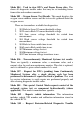
Mode $04 – Used to clear DTCs and Freeze Frame data. This clears all diagnostic trouble codes that may be set including freeze frame data and readiness monitors. Mode $05 – Oxygen Sensor Test Results. This mode displays the oxygen sensor monitor screen and the test results gathered about the oxygen sensor. There are ten numbers available for diagnostics: 1. 2. 3. 4. 5. 6. 7. 8. 9. $01 Rich-to-Lean O2 sensor threshold voltage. $02 Lean-to-Rich O2 sensor threshold voltage.
Codes with Permanent Status. This mode is required for all emissions-related DTCs. The presence of permanent DTCs at an inspection without the MIL illuminated is an indication that a proper repair was not verified by the on-board monitoring system.
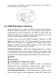
3. Using the Scan Tool 3.1 Tool Description 1) 2) 3) OBD II CONNECTOR -- Connects the scan tool to the vehicle‟s Data Link Connector (DLC). LCD DISPLAY -- Indicates test results. GREEN LED – Indicates that engine systems are running normally (The number of monitors on the vehicle which are active and performing their diagnostic testing is in the allowed limit, and no DTCs are present).
4) YELLOW LED – Indicates there is a possible problem. A “Pending” DTC is present and/or some of the vehicle‟s emission monitors have not run their diagnostic testing. 5) RED LED – Indicates there is a problem in one or more of the vehicle‟s systems. The red LED is also used to show that DTCs are present. DTCs are shown on the Scan Tool‟s display. In this case, the MIL lamp on the vehicle‟s instrument panel will light steady on.
recording customized live data list, and views next frames of data when playing back live data. 13) DOWN SCROLL BUTTON -- Moves down through menu and submenu items in menu mode. When more than one screen of data is retrieved, moves down through the current screen to next screens for additional data. 14) USB CONNECTOR -- Connects the scan tool to the PC for printing and upgrading. 3.
“$” -- Identifies the control module number from which data is retrieved. Indicates the Test ID in On-Board Mon. Test. 2) “?” -- Indicates help or code breaker information is available. 3) “G” -- Indicates graphic viewing is available. 1) 3.5 Keyboard No solvents such as alcohol are allowed to clean the keypad or display. Use a mild nonabrasive detergent and a soft cotton cloth. Do not soak the keypad as the keypad is not waterproof. 3.
Figure 3.1 2) From DTC Lookup screen, use the LEFT/RIGHT button to move to the desired character, use the UP/DOWN button to change selected digit/character and press the OK button to confirm. (Figure 3.2) DTC Lookup P0001 OK ESC Left Right Change digit Confirm Exit [ ][ ]- Change Digit [ENTER]- Figure Confirm3.2 [ESC]- Exit 3) View the DTC definition on screen.
In the Code Breaker screen, there are three options to assist user to understand DTC more: System Description and Quick Check to read detailed description of DTCs, General Notes to view helpful repair information of DTCs. 4) To view previous or next DTC in the built-in DTC library, use the LEFT/RIGHT button. 5) To enter another DTC, press the ESC button to return to previous screen. 6) To exit to Main Screen, press the ESC button. 3.
System Setup Language Work Mode Configure Monitors Unit of Measure Key Beep Set Status Beep Set Tool Self-test 1/8 ? Figure 3.3 Language Setup English is the default language. 1) From System Setup screen, use the UP/DOWN scroll button to select Language, and press the OK button. 2) Use the UP/DOWN scroll button to select the desired language and press the OK button to save your selection and return to previous screen. We provide three language options currently.
Work Mode Scan Tool Mode Ready Test Mode 1/2 ? Figure 3.5 The scan tool can work in two modes: Scan Tool Mode and Ready Test Mode. The former is used to check the I/M readiness monitor status before performing OBD II diagnostics; the latter is used to perform the I/M readiness monitor status quick-check to determine if the tested vehicle is ready for an emission test.
From System Setup screen, use the UP/DOWN scroll button to select Configure Monitors, and press the OK button. (Figure 3.6 ) Configure Monitors 1/4 Spark IGN Required Monitors Compression IGN Required Monitors Allowed INC Monitors ? Reset Factory Default Figure 3.6 In this menu, you could configure the monitors required to test spark ignition and compression ignition, the number of monitors to pass diagnosis, and restore the default settings.
The monitors for compression ignition engines show as below: Compression IGN Required Monitors □ √ √ √ √ 3) √ √ √ √ MIS FUEL CCM HCCAT NCAT BP EGS PM EGR Allowed INC Monitors From Configure Monitors screen, use the UP/DOWN scroll button to select Allowed INC Monitors, and press the OK button. Emissions tests vary depending on the geographic or regional area in which the vehicle is registered.
2) From Unit of Measure screen, use the UP/DOWN scroll button to select the desired unit of measurement. (Figure 3.7 ) Unit of Measure English Metric 1/2 ? Figure 3.7 3) Press the OK button to save your selection and return to previous menu. Key Beep Set This function allows you to turn on/off the build-in speaker for Key pressing. The default setting is Beep On. 1) From System Setup screen, use the UP/DOWN scroll button to select Key Beep Set and press the OK button.
3) Press the OK button to save your selection and return to previous menu. Status Beep Set This function allows you to turn on/off the build-in speaker for the LEDs in diagnostic testing. Different audio tone corresponds to different LED lamp. This function is invaluable when working in bright areas where LED illumination alone is not sufficient. 1) From System Setup screen, use the UP/DOWN scroll button to select Status Beep Set and press the OK button.
1) From System Setup screen, use the UP/DOWN scroll button to select Tool Self-test, and press the OK button. 2) Select Display Test from Tool Self-test menu and press the OK button to start test. (Figure 3.10 ) Tool Self-test 1/3 Display Test Keyboard Test LED Test ? Figure 3.10 3) 4) B. Look for missing spots in the red, green, blue, black and white LCD display. When completed, press the ESC button to exit. Keyboard Test The Keyboard Test function verifies if the keys are functioning properly.
3) C. Double press ESC to return to previous menu. LED Test The LED Test function verifies if the I/M Readiness LED indicator lamps are functioning properly. 1) Use the UP/DOWN scroll button to select LED Test from the Tool Self-test menu, and then press the OK button. LED Test LED Test…. Press any key to exit. Figure 3.12 2) Three LED lamps will be flickering in turn at different frequencies. 3) Press any key to exit and return to previous menu.
3) Connect the scan tool to your computer through the USB cable provided. 4) From System Setup screen in scan tool, use the UP/DOWN scroll button to select Update Mode, and press the OK button. 5) Select the programs to be updated in your computer. There are two types of programs: operating system and DTC library. (Figure 3.13) 6) Click Update in the MaxiLink Tool Kit window to begin updating. Figure 3.13 7) During the update procedure, the scan tool displays a message “Update Program.
Update Mode forcedly. Then follow the update procedure to refresh the program. 3.9 About The About function allows viewing of some important information such as serial number and software version number of the scanner. 1) From Main Screen, use the UP/DOWN scroll button and LEFT/RIGHT scroll button to select About and press the OK button; wait for the About screen to appear. 2) View tool information on screen. Figure 3.14 3.
vehicles. If the vehicle is OBD II compliant, the label will designate “OBD II Certified”. Additionally, Government regulations mandate that all OBD II compliant vehicles must have a “common” sixteen-pin Data Link Connector (DLC). For your vehicle to be OBD II compliant it must have a 16-pin DLC (Data Link Connector) under the dash and the Vehicle Emission Control Information Label must state that the vehicle is OBD II compliant. 3.
If the scan tool won‟t power up or operates incorrectly in any other way, you need to do the following to check up: Check if the scan tool‟s OBD II connector is securely connected to the vehicle‟s DLC; Check if the DLC pins are bent or broken. Clean the DLC pins if necessary. Check vehicle battery to make sure it is still good with at least 8.0 volts.
4. Review Data The Review Data function allows viewing of data from last test recorded by the scan tool. 1) Use the UP/DOWN scroll button and LEFT/RIGHT scroll button to select Review Data from Main Screen, and press the OK button. (Figure 3.1) 2) Use the UP/DOWN scroll button to select the desired item from Review Data menu, and press the OK button. (Figure 4.1 ) Review Data 1/6 Live Data Pending Codes View Freeze Frame I/M Readiness On-Board Mon. Test Modules Present Figure 4.
3) Review selected data on screen. (Figure 4.3 ) 1/1 C1201 Engine Control System Malfunction ? Figure 4.3 NOTE: If there is no data stored for selected item, a “Not Supported or Stored No Data!” message shows on the screen.
5. OBDII Diagnostics When more than one vehicle control module is detected by the scan tool, you will be prompted to select the module where the data may be retrieved. The most often to be selected are the Power train Control Module [PCM] and Transmission Control Module [TCM]. CAUTION: Don’t connect or disconnect any test equipment with ignition on or engine running. 1) 2) 3) 4) 5) Turn the ignition off. Locate the vehicle‟s 16-pin Data Link Connector (DLC).
Review previously erasing.(Figure 5.1) stored data thoroughly before Diagnostic Erase previously stored data to save data from this test? YES NO Figure 5.1 If no data is stored in the scan tool, above prompt will not show up. 8) If you wish to erase the data, press the OK button; if you do not want to erase the data, press ESC to exit or use LEFT/RIGHT button to select NO and press OK to continue. 9) View a summary of system status (MIL status, DTC counts, Monitor status) on screen. (Figure 5.
Control Module Engine Module $A4 1/2 ? Figure 5.3 Use the UP/DOWN scroll button to select a module and press the OK button. 5.1 Read Codes Reading Codes can be done with the key on engine off (KOEO) or with the key on engine running (KOER). Stored Codes are also known as “hard codes” or “permanent codes”. These codes cause the control module to illuminate the malfunction indicator light (MIL) when emission-related fault occurs.
Diagnostic Menu 1/11 Read Codes Erase Codes Live Data View Freeze Frame I/M Readiness O2 Monitor Test ? Figure 5.4 2) Use the UP/DOWN scroll button to select Stored Codes or Pending Codes from the Read Codes menu and press the OK button. Read Codes 1/3 Stored Codes Pending Codes Permanent Codes ? Figure 5.5 If there is not any Diagnostic Trouble Code, the display indicates “No (pending) codes are stored in the module!” Wait a few seconds or press any key to return to previous screen.
1/1 P1633 $10 BUICK Ignition 0 Switch Circuit ? Figure 5.6 4) If more than one DTC is found, use the LEFT/RIGHT scroll button to check all the codes. If retrieved DTCs contain any manufacturer specific or enhanced codes, a “Manufacturer specific codes are found! Press any key to select vehicle make!” message comes up prompting you to select vehicle manufacturer to view DTC definitions. Use UP/DOWN scroll button to select manufacturer and then press OK button to confirm.
enhanced data. Further, the I/M Readiness Monitor Status for all vehicle monitors is reset to Not Ready or Not Complete status. Do not erase the codes before the system has been checked completely by a technician. NOTE: Erasing codes does not mean that trouble codes in ECU have been eliminated completely. As long as there is fault with the vehicle, the trouble codes keeps on presenting. This function is performed with key on engine off (KOEO). Do not start the engine.
Erase Codes Erase Done! Press any key to con. Figure 5.9 If the codes are not cleared, then an “Erase Failure. Turn Key on with Engine off!” message appears. Erase Codes Erase Failure. Turn Key on with Engine Off! Press any key to con. Figure 5.10 4) Press any button to return to Diagnostic Menu. 5.3 Live Data In this function, you can not only read the live data but also record data for later review.
2) Wait a few seconds while the scan tool validates the PID MAP. (Figure 5.11) Live Data Reading PID.01 - Please Wait - Figure 5.11 3) Use the UP/DOWN scroll button to select View Data from Live Data menu and press the OK button. ……………… .Live Data View Data Record Data Playback Data 1/3. ? Figure 5.12 Viewing Complete Data Set 1) To view complete set of data, use UP/DOWN scroll button to select Complete Data Set from View Data menu and press the OK button.
…………………View Data 1/3. Complete Data Set Custom Data Set Unit of Measure ? Figure 5.13 2) View live PIDs on the screen. Use the UP/DOWN scroll button for more PIDs if additional information is available on more than one page. Live Data DTC_CNT FUELSYS1 FUELSYS2 LOAD_PCT (%) ETC(℃) SHRTFT1 (%) 6 0 0L -- ? 0.0 -40 99.2 Figure 5.14 The number “x” to the right of the screen indicates sequence of the highlighted item. To view full name of the highlighted PID, press the ○ ? button.
Figure 5.15 3) Press the ESC button to return to previous menu. Viewing Custom Data Set 1) To view customized PID data, use the UP/DOWN scroll button to select Custom Data Set from View Data menu and press the OK button. (Figure 5.13) 2) Observe on-screen instructions. ……………Custom Data Set……… ….. [ ] – Select/Deselect [ ] – Deselect all [OK] – Confirm [ESC] – Cancel Press any key to continue. Figure 5.
…………..Custom Data Set DTC_CNT FUELSYS1 FUELSYS2 LOAD_PCT ECT SHRTFT1 4/26 #01 ? Figure 5.17 The number “x” to the upper right corner of the screen indicates sequence of highlighted item; and “#x” are the order that the parameters are selected and will be displayed. If you want to deselect all marked items or select all items, press the LEFT button. A message comes up to ask for your confirmation. ………………Deselect All…………………. Deselect all selected PID’s? YES NO Figure 5.
………………….Live Data DTC_CNT FUELSYS2 ETC(℃) SHRTFT1 (%) 4. 0 0L -40 99.2 ? Figure 5.19 5) Use the ESC button to return to previous menu. Recording Data The Record Data function allows recording vehicle modules’ Parameter Identification (PID) data to help diagnose intermittent vehicle problems. A recording includes 5 frames of live data before trigger event and several frames after trigger event. There are two trigger modes used to record data: A.
………………..Record Data 1/3.. Complete Data Set Custom Data Set Unit of Measure ? Figure 5.20 2) Use the UP/DOWN scroll button to select a trigger mode and press the OK button. …….……Pick Trigger Mode Manual Trigger DTC Trigger 1/2 ? Figure 5.21 3) If data from previously tested vehicle is not erased, data from current test will be stored in a temporary cache. Use the UP/DOWN scroll button to select a memory location and press the OK button. …………….
The asterisk (*) icon on the screen indicates that there is a previous recording in the memory location. If you select a location marked with an asterisk (*) icon, a message prompting to overwrite old recording displays. Select Memory ... A previous recording exists! Do you want to overwrite it? YES NO Figure 5.
………………….DTC Trigger…………….. Waiting for DTC to trigger recording… Press [ESC] to exit Figure 5.25 5) Wait for DTC to trigger recording or press OK to start recording. (Figure 5.26) Drive till a DTC is detected when DTC Trigger is selected. If no DTCs are detected, press ESC to exit recording. …….Recording…. DTC_CNT FUELSYS1 FUELSYS2 LOAD_PCT(%) ETC(℃) SHRTFT1(%) 5/46 ….. 0 0L -0.0 -40 99.2 ? Figure 5.26 6) The number “x/x...
Record Data Recording Done! Playback data? YES NO Figure 5.27 If you wish to playback recorded data, press the OK button; if you do not wish to playback, press the ESC button, or use LEFT/RIGHT button to select NO and press the OK button to return to Record Data menu. Recording Custom Data Set 1) To record customized data, use the UP/DOWN scroll button to select Custom Data Set from Record Data menu and press the OK button. (Figure 5.20) 2) Observe on-screen instructions. (Figure 5.16).
4) Use the UP/DOWN scroll button to select a trigger mode and press the OK button.( Figure 5.21) 5) Use the UP/DOWN scroll button to select a memory location and press the OK button.( Figure 5.22) 6) If data from previously tested vehicle is not erased, data from current test will be stored in temporary cache. The asterisk (*) icon on the screen indicates that there is a previous recording in the memory location.
Playback Data The Playback Data function allows viewing of previously stored PID data. 1) To playback recorded data, use the UP/DOWN scroll button to select Playback Data from Live Data menu and press the OK button. (Figure 5.12) 2) You are also allowed to playback recorded data immediately after recording. Use the UP/DOWN button to select the memory location marked with an asterisk (*) icon. Select Memory Location #1 Location #2 Location #3 * * 3/3 ? Figure 5.
4) Use the LEFT/RIGHT button to view PIDs of next or previous frames. 6 of 135 frame DTC_CNT FUELSYS1 FUELSYS2 LOAD_PCT(%) ETC(℃) SHRTFT1(%) 0 OL N/A 0.0 -40 99.2 4 ? Figure 5.30 5.4 Viewing Freeze Frame Data Freeze Frame Data allows the technician to view the vehicle‟s operating parameters at the moment a DTC (Diagnostic Trouble Code) is detected. For example, the parameters may include engine speed (RPM), engine coolant temperature (ECT), or vehicle speed sensor (VSS) etc.
…………View Freeze Frame DTCFRZF FUELSYS1 FUELSYS2 LOAD_PCT (%) ECT(℃) SHRTFT1 (%) 2. P1633 OL -0.0 ? -40 99.2 Figure 5.31 4) If there is no freeze frame data available, an advisory message “No freeze frame data stored!” shows on the display. If you want to view full name of a PID, use the UP/DOWN scroll button to select the PID, and press the HELP button. ……………… ..FUELSYS1……… ……. Fuel System 1 Status Figure 5.32 5) Press ESC button to return to previous screen. 5.
complete drive cycle with no trouble codes in memory. Times for reset vary depending on vehicle. Some latest vehicle models may support two types of I/M Readiness tests: A. B. Since DTCs Cleared - indicates status of the monitors since the DTCs are erased. This Drive Cycle - indicates status of monitors since the beginning of the current drive cycle. An I/M Readiness Status result of “NO” does not necessarily indicate that the vehicle being tested will fail the state I/M inspection.
4) Use the UP/DOWN scroll button, as necessary, to view the status of the MIL light (“ON” or “OFF) and the following monitors: Misfire monitor -- Misfire monitor Fuel System Mon -- Fuel System Monitor Comp.
6) Press the ESC button to return to Diagnostic Menu. 5.6 O2 Monitor Test OBD2 regulations set by SAE require that relevant vehicles monitor and tests on the oxygen (O2) sensors to identify problems related to fuel efficiency and vehicle emissions. These tests are not on-demand tests and they are done automatically when engine operating conditions are within specified limits. These test results are saved in the on-board computer's memory.
If the vehicle does not support the mode, an advisory message will be displayed on the screen. …………….O2 Monitor Test………….. The selected mode is not supported! Figure 5.37 4) View test results of selected O2 sensor. … ……….O2 Bank1 Sensor2 Rich-Lean Threshd V Lean-Rich Threshd V Low for Switch (V) High for Switch (V) Rich-Lean Threshd S Lean-Rich Threshd S 1/31. ? Figure 5.38 5) Use the UP/DOWN scroll button to view more screens of data if additional information is available in more than one page.
test results for emission-related power train components and systems that are and are not continuously monitored. Test and components IDs are determined by the vehicle manufacturer. In this test, there are typically a minimum value, a maximum value, and a current value for each monitor. By comparing the current value with the minimum and maximum value, the scan tool will determine if it is OK. 1) Use the UP/DOWN scroll button to select On-Board Mon. Test from Diagnostic Menu and press the OK button.
5) From On-Board Mon. Test menu, use the UP/DOWN scroll button to select a test to view and press the OK button. Or, use the LEFT/RIGHT scroll button to view previous/next screen of test items. If the vehicle under test does not support the mode, an advisory message will be displayed on the screen. On-Board Mon. Test The selected mode is not supported Press any key to con.. Figure 5.41 For CAN-equipped vehicles, test selections can be as below: On-Board Mon. Test O2 Mon. B1S1 O2 Mon. B1S2 O2 Mon.
HO2S11 Voltage amplitu ID MOD TEST(volts) MIN(volts) MAX(volts) STS 11 $10 400 1E1 ----OK ? Figure 5.43 NOTE: If the On-Board Monitor Test failed, this monitor item will be red color. Just by the text color you may easily find out which system is at fault. EVAP monitor Phase 0 Initial tank vacuum an.. Figure 5.44 Phase 0 Initial tank vacuum ID MOD TEST(in H2O) MIN(in H2O) MAX(in H2O) STS 00 $10 0000 7000 7200 Fail ? Figure 5.45 8) Press ESC button to return to the previous menus. 5.
The Component Test function allows initiating a leak test for the vehicle's EVAP system. The scan tool itself does not perform the leak test, but commands the vehicle's on-board computer to start the test. Different vehicle manufacturers might have different criteria and methods for stopping the test once it has been started. Before starting the Component Test, refer to the vehicle service manual for instructions to stop the test.
support the EVAP Leak Test, an advisory message is displayed on the screen. .............Component Test The selected mode is not supported Press any key to con. Figure 5.48 4) Wait a few seconds or press any key to return to previous screen. 5.9 Viewing Vehicle Information The Vehicle Info. function enables retrieval of Vehicle Identification No. (VIN), Calibration ID Nos. (CINs), Calibration Verification Nos. (CVNs) and In-use Performance Tracking on 2000 and newer vehicles that support Mode 9.
Vehicle Info. Reading info… - Please Wait - Figure 5.50 If the vehicle does not support this mode, a message shows on the display warning that the mode is not supported. 4) From Vehicle Info. Menu, use the UP/DOWN scroll button to select an available item to view and press the OK button. Vehicle Info. 3/3 Vehicle ID Number Calibration ID Cal. Verf. Number ? Figure 5.51 5) View retrieved vehicle information on screen. Cal. Verf. Number CVN1: BB BA A0 78 ? Figure 5.
5.10 Modules Present The Modules Present function allows viewing of the module IDs and communication protocols for OBD2 modules in the vehicle. 1) Use the UP/DOWN scroll button to select Modules Present from Diagnostic Menu and press OK button. (Figure 5.4) 2) View modules present with their IDs and communication protocols. Modules Present ID Protocol _________________________ $00 ISO 9141-2 ? Figure 5.53 3) Press the ESC button to return to previous menu 5.
1/11 U0101 $07E8 Lost Communication with TCM ? Figure 5.54 1) Press the ○ ? Help button to display Code Breaker menu. Code Breaker 1/3 System Description Quick Check General Notes Figure 5.55 2) Click on System Description and Quick Check to read detailed descriptions of DTCs. 3) Click on General Notes to view helpful repair information of DTCs. 4) To return to previous screen, press ESC button.
6. Print Data The Print Data function allows printing out diagnostic data recorded by the scan tool or customized test reports. To print out retrieved data, you need the following tools: Autolink AL519 scan tool A PC or laptop with USB ports A USB cable 1) 2) 3) Install Maxi-Link applications through the included CD, or downloading the applications from our website: www.auteltech.com or our distributors‟ site. Connect the scanner to computer with the USB cable supplied.
Print Data Stored Codes Pending Codes Live Data Freeze Frame I/M Readiness O2 Sensor Test Print All Data 1/9 ? Figure 6.2 6) 7) To print all retrieved data, use the UP/DOWN scroll button to select Print All Data from Print Data menu. Press the OK button to upload data to the computer. In the Maxi-Link Tool Kit, you could edit, delete, copy and print the data in the textbox by selecting the icons on the upper right of window. Print data. Delete data. Copy data. Edit data.
7. I/M Readiness One-Click Function The I/M Readiness One-Click Key on the scan tool shows you how quickly and easily a novice user can check the I/M readiness status, MIL state, and DTCs. By simple clicking on this key, the scan tool automatically checks the emission-related monitoring systems and reads DTCs. All data shows on one screen, which provides a simple profile of vehicle at a glance. There are two modes to show I/M readiness monitor status. You can configure work modes in the Setup menu. (see 3.
7.1 Ready Test Mode Repairs to the emissions-control systems of a 1996 or newer vehicle cause the vehicle‟s computer (ECU) memory to be cleared. The vehicle must go through a drive cycle to allow the ECU to perform a series of tests to ensure that the repair was successful, and before a state mandated emissions test can be conducted. Modern vehicles lack equipment to indicate whether the tests have been completed.
“OK” -- Indicates that a particular monitor being checked has completed its diagnostic testing. “INC” -- Indicates that a particular monitor being checked has not completed its diagnostic testing. “N/A” -- The monitor is not supported on the vehicle. The LED and audio tone indications are as interpreted below: LED Interpretation The green and red LEDs provide an easy way to check if emission-related monitoring systems complete their self-diagnostic testing.
7.2 Scan Tool Mode NOTE: Only in this mode can you perform the OBDII diagnostics. To enter this mode, please follow the steps in 5.5 Retrieving I/M Readiness Status. The green, yellow and red LEDs provide a quick way to help you determine if a vehicle is ready for an Emission Test.
NOTE: From the code retrieval procedure, determine the status of each Monitor. Take this information to an emissions professional to determine (based on your test results) if your vehicle is ready for an Emissions Test. 3) RED LED – Indicates there is a problem with one or more of the vehicle‟s system. A vehicle displaying a red LED is definitely not ready for an Emissions Test. The red LED is also an indication that there are DTCs present. The MIL lamp on the vehicle‟s instrument panel will light steady.
NOTE: The following audio tone description only works in Scan Tool mode. Different audio tone with different LED lights will indicates different I/M Readiness Status.
8. Warranty and Service 8.1 Limited One Year Warranty Autel warrants to its customers that this product will be free from all defects in materials and workmanship for a period of one (1) year from the date of the original purchase, subject to the following terms and conditions: 1) The sole responsibility of Autel under the Warranty is limited to either the repair or, at the option of Autel, replacement of the scan tool at no charge with Proof of Purchase. The sales receipt may be used for this purpose.