Table of Contents 1. 2. 3. 4. 5. 6. SAFETY PRECAUTIONS AND WARNINGS .............................................. 1 GENERAL INFORMATION .......................................................................... 2 2.1 ON-BOARD DIAGNOSTICS (OBD) II ............................................................. 2 2.2 DIAGNOSTIC TROUBLE CODES (DTCS) ........................................................ 2 2.3 LOCATION OF THE DATA LINK CONNECTOR (DLC) .................................... 3 2.
1. Safety Precautions and Warnings To prevent personal injury or damage to vehicles and/or the scan tool, read this instruction manual first and observe the following safety precautions at a minimum whenever working on a vehicle: Always perform automotive testing in a safe environment. Wear safety eye protection that meets ANSI standards. Keep clothing, hair, hands, tools, test equipment, etc. away from all moving or hot engine parts.
2. General Information 2.1 On-Board Diagnostics (OBD) II The first generation of On-Board Diagnostics (called OBD I) was developed by the California Air Resources Board (ARB) and implemented in 1988 to monitor some of the emission control components on vehicles. As technology evolved and the desire to improve the On-Board Diagnostic system increased, a new generation of On-Board Diagnostic system was developed. This second generation of On-Board Diagnostic regulations is called "OBD II".
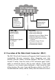
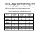
DTC Example P0202 Systems B=Body C=Chassis P=Powertrain U=Network Identifying specific malfunctioning section of the systems Code Type Generic (SAE): P0, P2, P34-P39 B0, B3 C0, C3 U0, U3. Manufacturer Specific: P1, P30-p33 B1, B2 C1, C2 U1, U2 Sub-systems 1= Fuel and Air Metering 2= Fuel and Air Metering 3= Ignition System or Engine Misfire 4= Auxiliary Emission Controls 5= Vehicle Speed Control and Idle Controls 6= Computer Output Circuits 7= Transmission Controls 8= Transmission Controls 2.
the connector. If the DLC cannot be found, refer to the vehicle‟s service manual for the location. 2.4 OBD II Readiness Monitors An important part of a vehicle‟s OBD II system is the Readiness Monitors, which are indicators used to find out if all of the emissions components have been evaluated by the OBD II system. They are running periodic tests on specific systems and components to ensure that they are performing within allowable limits.
operated under specific conditions before the monitor is ready. These monitors are termed non-continuous monitors and are listed below: 1) 2) 3) 4) 5) 6) 7) 8) EGR System O2 Sensors Catalyst Evaporative System O2 Sensor Heater Secondary air Heated Catalyst A/C system 2.5 OBD II Monitor Readiness Status OBD II systems must indicate whether or not the vehicle‟s PCM‟s monitor system has completed testing on each component.
stop and go, city type driving, and at least one overnight-off period. For specific information on getting your vehicle‟s OBD monitor system ready, please consult your vehicle owner‟s manual. 2.6 OBD II Definitions Power-train Control Module (PCM) -- OBD II terminology for the on-board computer that controls engine and drive train. Malfunction Indicator Light (MIL) -- Malfunction Indicator Light (Service Engine Soon, Check Engine) is a term used for the light on the instrument panel.
faults can be detected. Drive cycles vary depending on the vehicle and the monitor that needs to be reset. For vehicle specific drive cycle, consult the vehicle‟s Owner‟s Manual. Freeze Frame Data -- When an emissions related fault occurs, the OBD II system not only sets a code but also records a snapshot of the vehicle operating parameters to help in identifying the problem.
Mode $04 - Used to clear DTCs and Freeze Frame data. This clears all diagnostic trouble codes that may be set including freeze frame data and readiness monitors. Mode $05 - Oxygen Sensor Test Results. This mode displays the oxygen sensor monitor screen and the test results gathered about the oxygen sensor. There are ten numbers available for diagnostics: 1. 2. 3. 4. 5. 6. 7. 8. 9.
Mode $10 -- Request Emission-Related Diagnostic Trouble Codes with Permanent Status. This mode is required for all emissions-related DTCs. The presence of permanent DTCs at an inspection without the MIL illuminated is an indication that a proper repair was not verified by the on-board monitoring system.
3. Using the Scan Tool 3.1 Tool Description ① OBD II CONNECTOR -- Connects the scan tool to the vehicle‟s Data Link Connector (DLC). ② LCD DISPLAY -- Indicates test results. ③ GREEN LED – Indicates that engine systems are running normally (The number of monitors on the vehicle which are active and performing their diagnostic testing is in the allowed limit, and no DTCs are present).
④ YELLOW LED – Indicates there is a possible problem. A “Pending” DTC is present and/or some of the vehicle‟s emission monitors have not run their diagnostic testing. ⑤ RED LED – Indicates there is a problem in one or more of the vehicle‟s systems. The red LED is also used to show that DTCs are present. DTCs are shown on the Scan Tool‟s display. In this case, the MIL lamp on the vehicle‟s instrument panel will light steady on.
2) 3) OBD2 cable -- Provides power to tool and communicates between tool and vehicle. USB cable -- Allows easy update via a PC and an internet connection. 3.4 Navigation Characters Characters used to help navigate the scan tool are: 1) “#” -- Identifies the control module number from which data is retrieved. 2) “Pd” – Identifies a pending DTC when viewing DTCs. 3.5 Keyboard No solvents such as alcohol are allowed to clean the keypad or display. Use a mild nonabrasive detergent and a soft cotton cloth.
6) 7) 8) Status Beep Set: Turns on/off the I/M Readiness Status beep. Tool Self-test: Checks if the LCD display, LED lamps and keyboard are working normally. Update Mode: Accesses the Update Mode. Settings of the unit will remain until change to the existing settings is made. To enter the Setup menu When the scan tool is powered on, it displays a Main Screen. (Figure 3.1) Figure 3.1 From the Main Screen: Use the SCROLL button to select Setup, and press the ENTER button.
Language Setup English is the default language. 1) From System Setup screen, use the SCROLL button to select Language, and press the ENTER button. 2) Use the SCROLL button to select the desired language and press the ENTER button to save your selection and return to previous screen. We provide three language options currently. (Figure 3.3) Language 1/3 English Français Español Figure 3.3 Work Mode From System Setup screen, use the SCROLL button to select Work Mode, and press the ENTER button.
perform the I/M readiness monitor status quick-check to determine if the tested vehicle is ready for an emission test. Use the SCROLL button to select Scan Tool Mode or Ready Test Mode and press the ENTER button to save your selection and return to previous screen. 1) Scan Tool Mode Scan Tool Mode is the default work mode. In this mode, after the vehicle‟s monitors have run and completed their diagnosis and testing, the scan tool will turn to OBDII diagnostic procedures.
In this menu, you could configure the number of monitors to pass diagnosis, and restore the default settings. 1) Allowed INC Monitors From Configure Monitors screen, use the SCROLL button to select Allowed INC Monitors, and press the ENTER button. Emissions tests vary depending on the geographic or regional area in which the vehicle is registered. So the scan tool provides a more flexible way to meet different standards, which allows the user to select 0, 1, 2, 3 „not complete‟ monitors in test.
Unit of Measure 1/2 English Metric Figure 3.6 3) Press the ENTER button to save your selection and return to previous menu. Key Beep Set This function allows you to turn on/off the build-in speaker for Key pressing. The default setting is Beep On. 1) From System Setup screen, use the SCROLL button to select Key Beep Set and press the ENTER button. 2) From Key Beep Set menu, use the SCROLL button to select Beep ON or Beep OFF to turn on/off the beep. (Figure 3.
Status Beep Set This function allows you to turn on/off the build-in speaker for the LEDs in diagnostic testing. Different audio tone corresponds to different LED lamp. This function is invaluable when working in bright areas where LED illumination alone is not sufficient. 1) From System Setup screen, use the SCROLL button to select Status Beep Set and press the ENTER button. 2) From Status Beep Set menu, use the SCROLL button to select Beep ON or Beep OFF to turn on/off the beep.
2) Select Display Test from Tool Self-test menu and press the ENTER button to start test. (Figure 3.9 ) Tool Self-test 1/4 Display Test Keyboard Test LED Test Previous Menu 3) 4) B. Figure 3.9 Look for missing spots in the red, green, blue, black and white LCD display. When completed, press the ENTER button to exit. Keyboard Test The Keyboard Test function verifies if the keys are functioning properly.
C. LED Test The LED Test function verifies if the I/M Readiness LED indicator lamps are functioning properly. 1) Use the SCROLL button to select LED Test from the Tool Self-test menu, and then press the ENTER button. 2) In the LED Self-test menu, use the SCROLL button to select one or more LED lamps to check. The LED should turn on or off according to the selected commands. LED Self-test 1/4 RED LED ON YELLOW LED ON GREEN LED ON Previous Menu Figure 3.
4) From System Setup screen in scan tool, use the SCROLL button to select Update Mode, and press the ENTER button. 5) Select the programs to be updated in your computer. There are two types of programs: operating system and DTC library. (Figure 3.12) 6) Click Update in the MaxiLink Tool Kit window to begin updating. Figure 3.12 7) During the update procedure, the scan tool displays a message “Update Program. Please wait…”.
To exit the Setup menu Use the SCROLL button to select Previous Menu from the System Setup screen, and press the ENTER button to return to Main Screen. 3.8 About The About function allows viewing of some important information such as serial number and software version number of the scanner. 1) From Main Screen, use the SCROLL button to select About and press the ENTER button; wait for the About screen to appear. 2) View tool information on screen.(Figure 3.13) Figure 3.13 3.
compliant, check the Vehicle Emissions Control Information (VECI) Label which is located under the hood or by the radiator of most vehicles. If the vehicle is OBD II compliant, the label will designate “OBD II Certified”. Additionally, Government regulations mandate that all OBD II compliant vehicles must have a “common” sixteen-pin Data Link Connector (DLC).
Scan tool doesn’t power up If the scan tool won‟t power up or operates incorrectly in any other way, you need to do the following to check up: Check if the scan tool‟s OBD II connector is securely connected to the vehicle‟s DLC; Check if the DLC pins are bent or broken. Clean the DLC pins if necessary. Check vehicle battery to make sure it is still good with at least 8.0 volts.
4. OBDII Diagnostics When more than one vehicle control module is detected by the scan tool, you will be prompted to select the module where the data may be retrieved. The most often to be selected are the Power train Control Module [PCM] and Transmission Control Module [TCM]. CAUTION: Don’t connect or disconnect any test equipment with ignition on or engine running. 1) 2) 3) 4) 5) Turn the ignition off. Locate the vehicle‟s 16-pin Data Link Connector (DLC).
7) View a summary of system status (MIL status, DTC counts, Monitor status) on screen. (Figure 4.1 ) Wait a few seconds or press any key for Diagnostic Menu (Figure 4.3) to come up. System Status MIL Status Codes Found Monitors N/A Monitors OK Monitors INC ON 6 3 3 5 Figure 4.1 If more than one module is detected, you will be prompted to select a module before testing. (Figure 4.2 ) Control Module 1/2 Engine Module $A4 Figure 4.
Pending Codes are also referred to as “maturing codes” or “continuous monitor codes”. They indicate problems that the control module has detected during the current or last driving cycle but are not considered serious yet. Pending Codes will not turn on the malfunction indicator lamp (MIL). If the fault does not occur within a certain number of warm-up cycles, the code clears from memory. 1) Use SCROLL button to select Read Codes from Diagnostic Menu and press ENTER button.
NOTE: Permanent Codes function is available for merely vehicles supporting the CAN protocols. 3) View DTCs and their definitions on screen. Press ENTER button to return to previous screen. 1/1 P1633 $10 BUICK Ignition 0 Switch Circuit Figure 4.5 4) The control module number, sequence of the DTCs, total number of codes detected and type of codes (Generic or Manufacturer specific, Stored or Pending codes) will be observed on the upper right hand corner of the display.
5) If the manufacturer of your vehicle is not listed, use the SCROLL button to select Other and press the ENTER button. Select Previous Menu from the Read Codes screen, and press ENTER button to return to previous menu. 4.2 Erasing Codes CAUTION: Erasing the Diagnostic Trouble Codes may allow the scan tool to delete not only the codes from the vehicle’s on-board computer, but also “Freeze Frame” data and manufacturer specific enhanced data.
If you do not want to proceed with erasing codes, use SCROLL button to select NO to exit. A message of “Command Cancelled!” show ups. Wait a few seconds or press any key to return to Diagnostic Menu. 3) Press the ENTER button to confirm. If the codes are cleared successfully, an “Erase Done!” confirmation message shows on the display. Erase Codes Erase Done! Press any key to con. Figure 4.8 If the codes are not cleared, then an “Erase Failure. Turn Key on with Engine off!” message appears.
(VSS) etc. This information will aid the technician by allowing the parameters to be duplicated for diagnostic and repair purposes. 1) To view freeze frame data, use the SCROLL button to select View Freeze Frame from Diagnostic Menu and press the ENTER button. (Figure 4.3) 2) Wait a few seconds while the scan tool validates the PID MAP. 3) If retrieved information covers more than one screen, use the SCROLL button, as necessary, until all the data have been shown up.
complete drive cycle with no trouble codes in memory. Times for reset vary depending on vehicle. Some latest vehicle models may support two types of I/M Readiness tests: A. Since DTCs Cleared - indicates status of the monitors since the DTCs are erased. B. This Drive Cycle - indicates status of monitors since the beginning of the current drive cycle. An I/M Readiness Status result of “NO” does not necessarily indicate that the vehicle being tested will fail the state I/M inspection.
4) Use the SCROLL button, as necessary, to view the status of the MIL light (“ON” or “OFF) and the following monitors: Misfire monitor -- Misfire monitor Fuel System Mon -- Fuel System Monitor Comp.
6) Press the ENTER button to return to Diagnostic Menu. 4.5 Viewing Vehicle Information The Vehicle Info. function enables retrieval of Vehicle Identification No. (VIN), Calibration ID Nos. (CINs), Calibration Verification Nos. (CVNs) and In-use Performance Tracking on 2000 and newer vehicles that support Mode 9. 1) Use SCROLL button to select Vehicle Info. from the Diagnostic Menu and press ENTER button. (Figure 4.3) 2) An advisory message comes up to remind you.
If the vehicle does not support this mode, a message shows on the display warning that the mode is not supported. 4) From Vehicle Info. Menu, use the SCROLL button to select an available item to view and press the ENTER button. Vehicle Info. 3/4 Vehicle ID Number Calibration ID Cal. Verf. Number Previous Menu Figure 4.16 5) View retrieved vehicle information on screen. Cal. Verf. Number CVN1: BB BA A0 78 Figure 4.
5. I/M Readiness One-Click Function The I/M Readiness One-Click Key on the scan tool shows you how quickly and easily a novice user can check the I/M readiness status, MIL state, and DTCs. By simple clicking on this key, the scan tool automatically checks the emission-related monitoring systems and reads DTCs. All data shows on one screen, which provides a simple profile of vehicle at a glance. There are two modes to show I/M readiness monitor status. You can configure work modes in the Setup menu. (see 3.
5.1 Ready Test Mode Repairs to the emissions-control systems of a 1996 or newer vehicle cause the vehicle‟s computer (ECU) memory to be cleared. The vehicle must go through a drive cycle to allow the ECU to perform a series of tests to ensure that the repair was successful, and before a state mandated emissions test can be conducted. Modern vehicles lack equipment to indicate whether the tests have been completed.
“OK” -- Indicates that a particular monitor being checked has completed its diagnostic testing. “INC” -- Indicates that a particular monitor being checked has not completed its diagnostic testing. “N/A” -- The monitor is not supported on the vehicle. The LED and audio tone indications are as interpreted below: LED Interpretation The green and red LEDs provide an easy way to check if emission-related monitoring systems complete their self-diagnostic testing.
5.2 Scan Tool Mode NOTE: Only in this mode can you perform the OBDII diagnostics. To enter this mode, please follow the steps in 4.4 Retrieving I/M Readiness Status. The green, yellow and red LEDs provide a quick way to help you determine if a vehicle is ready for an Emission Test.
NOTE: From the code retrieval procedure, determine the status of each Monitor. Take this information to an emissions professional to determine (based on your test results) if your vehicle is ready for an Emissions Test. 3) RED LED – Indicates there is a problem with one or more of the vehicle‟s system. A vehicle displaying a red LED is definitely not ready for an Emissions Test. The red LED is also an indication that there are DTCs present. The MIL lamp on the vehicle‟s instrument panel will light steady.
NOTE: The following audio tone description only works in Scan Tool mode. Different audio tone with different LED lights will indicates different I/M Readiness Status.
6. Warranty and Service 6.1 Limited One Year Warranty Autel warrants to its customers that this product will be free from all defects in materials and workmanship for a period of one (1) year from the date of the original purchase, subject to the following terms and conditions: 1) The sole responsibility of Autel under the Warranty is limited to either the repair or, at the option of Autel, replacement of the scan tool at no charge with Proof of Purchase. The sales receipt may be used for this purpose.