Trademarks Autel®, MaxiSys®, MaxiDAS®, MaxiScan®, MaxiTPMS®, MaxiRecorder®, and MaxiCheck® are trademarks of Autel Intelligent Technology Corp., Ltd., registered in China, the United States and other countries. All other marks are trademarks or registered trademarks of their respective holders.
Safety Information For your own safety and the safety of others, and to prevent damage to the device and vehicles upon which it is used, it is important that the safety instructions presented throughout this manual be read and understood by all persons operating or coming into contact with the device. There are various procedures, techniques, tools, and parts for servicing vehicles, as well as in the skill of the person doing the work.
Safety Information Important Safety Instructions Do Not Turn the Volume Up Too Loud When Using Headphones Listening at high volumes that over-stimulate the ear for long periods of time may result in loss of hearing. SAFETY WARNINGS: Always perform automotive testing in a safe environment. Wear safety eye protection that meets ANSI standards. Keep clothing, hair, hands, tools, test equipment, etc. away from all moving or hot engine parts.
Contents SAFETY INFORMATION ............................................................................................ II CHAPTER 1 USING THIS MANUAL ...................................................................... 1 1.1 CONVENTIONS ............................................................................................... 1 1.1.1 Bold Text ............................................................................................. 1 1.1.2 Notes ...............................................
4.2.1 Vehicle Menu Layout ..........................................................................23 4.3 VEHICLE IDENTIFICATION ..................................................................................25 4.3.1 Auto VIN Scan ....................................................................................25 4.3.2 Manual VIN Input ...............................................................................26 4.3.3 Manual Vehicle Selection ......................................................
.1 NAVIGATION .................................................................................................67 6.1.1 Terminology .......................................................................................69 6.2 OPERATIONS .................................................................................................70 6.2.1 Home .................................................................................................71 6.2.2 Search Fix Features......................................
12.2 12.3 12.4 12.5 12.6 12.7 12.8 SUPPORT SCREEN LAYOUT .......................................................................... 100 MY ACCOUNT ......................................................................................... 101 USER COMPLAINT .................................................................................... 101 DATA LOGGING ........................................................................................ 104 COMMUNITIES.................................................
Chapter 1 Using This Manual This manual contains device usage instructions. Some illustrations shown in this manual may contain modules and optional equipment that are not included in your system. Contact your sales representative for availability of other modules and optional tools or accessories. 1.1 Conventions The following conventions are used. 1.1.1 Bold Text Bold emphasis is used to highlight selectable items such as buttons and menu options. Example: Tap OK. 1.1.
Using This Manual Conventions To use the camera: 1 Tap the Camera button. The camera screen opens. 2 Focus the image to be captured in the view finder. 3 Tap the blue circle. The view finder now shows the captured picture and auto-saves the taken photo.
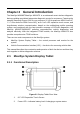
Chapter 2 General Introduction The MaxiSys MS906BT/MaxiSys MS906TS is an advanced smart wireless diagnostic device providing specialized automotive diagnostic service for customers. Featuring the powerful Samsung Exynos 5260 6-core processor (1.3 GHz quad-core ARM Cortex-A7 + 1.7 GHz dual-core ARM Cortex-A15), an 8.
General Introduction MaxiSys System Display Tablet 3. Ambient Light Sensor – detects ambient brightness 4. Microphone 5. TPMS Service Symbol – indicates the position of the embedded TPMS antenna (for MaxiSys MS906TS only) The power LED displays different colors in response to the following scenarios: A. Green Illuminates green when the Display Tablet is charging and the battery level is above 90%. B.
General Introduction MaxiSys System Display Tablet Figure 2-3 Display Tablet Top View 1. Mini SD Card Slot - holds the mini SD Card 2. Mini USB OTG Port 3. DC Power Supply Input Port - Connects the 12 volt power adapter to charge. 4. HDMI (high-definition multimedia interface) Port 5. USB Port 6. Headset Jack (3-Band 3.5mm ) 7. Lock/Power Button – turns the device on & off with long press, or locks the screen with short press 2.1.
General Introduction MaxiSys System Display Tablet AC/DC Power Supply The Display Tablet can be powered from a wall socket using the AC/DC power adapter. The AC/DC power supply also charges the internal battery pack. Vehicle Power The Display Tablet can be powered from the cigarette lighter or other suitable power port on the test vehicle through a direct cable connection. The vehicle power cable connects to the DC power supply port on the top side of the display unit. 2.1.
General Introduction Item Description Operating Temperature -10 to 55°C (14 to 131°F) Storage Temperature -20 to 70°C (-4 to 158°F) Housing Strong plastic housing with protective rubber boot Dimensions (W x H x D) 270.8 mm (10.0”) x 176.0 mm (6.9”) x 36.0 mm (1.4”) Weight NW: 1.10 kg (2.42 lb.) (for 906TS) Supported Automotive Protocols 2.
VCI – Wireless Diagnostic Interface General Introduction 1. Lighting Push Button – presses to turn on the white LED in the vehicle data connector socket 2. Power LED – indicates power and system status Green: illuminates solid green when powered on. Amber: flashes green and amber automatically when performing firmware update. Red: illuminates red automatically when powered up, and flashes red when system failure occurs. 3. Vehicle LED - flashes green when communicating with the vehicle’s system 4.
VCI – Wireless Diagnostic Interface General Introduction Dimensions (L x W x H) 87.0 mm (3.43”) x 52.0 mm (2.05”) x24.5 mm (0.96”) Weight 0.076 kg (0.168 lb.) Built-in Battery 3.7V Lithium Battery Light White LED 2.2.3 Power Sources The Wireless Diagnostic Interface operates on 12-volt vehicle power, which it receives through the vehicle data connection port. The unit powers on whenever it is connected to an OBD II/EOBD compliant data link connector (DLC). 2.3 Accessory Kit 2.3.
General Introduction Accessory Kit Mitsubishi/ Hyundai -12+16 PSA-2 Benz-38 Fiat-3 2.3.2 Other Accessories Mini USB Cable Connects the Display Tablet to the PC or the VCI unit. AC/DC External Power Adapter Connects the Display Tablet to the external DC power port for power supply. Compact Disc (CD) Includes the User Manual, Printing Services, VCI Update Agent, etc. Cigarette Lighter Provides power to the Display Tablet through connection to the vehicle’s cigarette lighter receptacle.
Chapter 3 Getting Started Make sure the Display Tablet has sufficient battery level or is connected to the DC power supply (see 2.1.2 Power Sources on page 5). NOTE: The images and illustrations depicted in this manual may differ from the actual ones. 3.1 Powering Up Press the Lock/Power button on the top right side of the Display Tablet to switch the unit on. The system boots up, and shows the lock screen. Pressing the inner ring with a Lock icon at the center displays 3 entry options: 1.
Getting Started Powering Up Figure 3-2 Sample MaxiSys MS906BT Job Menu 1. Application Buttons 2. Locator and Navigation Buttons 3. Status Icons NOTE: The screen is locked by default when you first turn on the Display Tablet. It is recommended to lock the screen to protect the information in the system and reduce the power consumption. Almost all operations on the Display Tablet are controlled through the touch screen.
Getting Started Powering Up Table 3-1 Applications Button Name Description Diagnostics Configures the unit to operate as a diagnostic tool. See Diagnostics Operations on page 19. Data Manager Opens the organization system for saved data files. See Data Manager Operations on page 84. TMPS Launches the TPMS service program directly. See TPMS Service Operations on page 55.
Getting Started Button Powering Up Name Description Training Allows you to store and play technical tutorial and training videos about the device usage or vehicle diagnostic techniques. See Training Operations on page 109. Quick Link Provides associated website bookmarks to allow quick access to product update, service, support and other information. See Quick Link Operations on page 113.
Getting Started Button Powering Up Name Description Camera Opens the camera with short press; takes and saves screenshot image with long press. The saved files are auto-stored in the Data Manager application for later reviews. See Data Manager Operations on page 84. Display Sound & Allows you to adjust the brightness of the screen and the volume of the audio output. MaxiSys Home Returns to MaxiSys Job Menu. VCI Opens the VCI Manager application.
Getting Started Powering Down By tapping on the bottom right corner, a Shortcuts Panel will be displayed, on which you are allowed to set various system settings of the tablet. Operations of each button on the panel are described in the table below: Table 3-3 Shortcuts Panel Buttons NOTE: The shortcuts buttons will be highlighted when enabled, and dimmed when disabled. Button 3.2 Name Description Calculator Launches calculator when pressed. Clock Launches clock when pressed.
Getting Started 3. Installing Computer Software Tap OK; the tablet will turn off in a few seconds. 3.2.1 Reboot System In case of system crash, press and hold the Lock/Power button for 8 seconds to reboot the system. 3.3 Installing Computer Software The MaxiSys MS906BT/MS906TS Diagnostic Platform allows you to print the information needed for your convenience. To realize the printing function, you need to install the printer driver program. To install the printer driver program 1.
Getting Started Installing Computer Software computer network, either via WiFi or LAN. See 9.1.3 Printing Setting on page 90 for more information. 3. Run the MaxiSys Printer program on the computer to open up the printer interface. 4. Click Test Print to make sure the printer is working successfully. 5. Tap the Print button on the toolbar. A temporary document will be created and sent to the computer for printing. 6.
Chapter 4 Diagnostics Operations By establishing a data link to the electronic control systems of the vehicle being serviced through the VCI device, the Diagnostics application allows you to retrieve diagnostic information, view live data parameters, and perform active tests. The Diagnostics application can access the electronic control module (ECM) for various vehicle control systems, such as engine, transmission, antilock brake system (ABS), airbag system (SRS) and more. 4.
Diagnostics Operations Establishing Vehicle Communication To connect to an OBD II vehicle 1. Insert the Vehicle Data Connector on the MaxiVCI V100 into the vehicle’s DLC, which is generally located under the vehicle dash. NOTE: The vehicle’s DLC is not always located under the dash; refer to the user manual of the test vehicle for additional connection information.
Diagnostics Operations Establishing Vehicle Communication communication is about 164 feet (about 50 m); this means you can perform vehicle diagnosis freely around the workshop with greater convenience.
Diagnostics Operations Establishing Vehicle Communication few seconds, and the Connection Mode LED on the MaxiVCI V100 illuminates solid green, indicating the connection between the devices is successful. The MaxiSys diagnostic platform is now ready to perform vehicle diagnosis. NOTE: When both the communication methods are applied at the same time, the MaxiSys system will use the USB communication as the default priority. 4.1.3 No Communication Message A. B.
Diagnostics Operations 4.2 Getting Started There is a loose connection. There is a blown vehicle fuse. There is a wiring fault on the vehicle or the adapter. There is a circuit fault in the adapter. Incorrect vehicle identification was entered. Getting Started Prior to first use of the Diagnostics application, make sure the VCI device has been synchronized with the Display Tablet to establish a communication link. See VCI Manager Operations on page 96. 4.2.
Diagnostics Operations Getting Started Top toolbar Buttons The operations of the Toolbar buttons at the top of the screen are listed and described in the table below: Table 4-1 Top Toolbar Buttons Button Name Description Home Returns to the MaxiSys Job Menu. VIN Scan All History Touching this button opens a dropdown list; tap Auto Detect for auto VIN detection; tap Manual Input to enter VIN manually. Displays all the vehicle makes in the vehicle menu.
Diagnostics Operations Vehicle Identification NOTE: The Update icon displayed on the upper right of the vehicle brand name indicates there is available update for the vehicle. Tap this icon to enter the Update application directly. 4.3 Vehicle Identification The MaxiSys diagnostic system supports four methods for Vehicle Identification. 1. Auto VIN Scan 2. Manual VIN Input 3. Manual Vehicle Selection 4. OBD Direct Entry 4.3.
Diagnostics Operations Vehicle Identification Figure 4-2 Sample Vehicle Diagnostics Screen In some cases when users have selected the vehicle brand instead of performing Auto VIN Scan in the first place, the system still provides an option for vehicle VIN scan. Figure 4-3 Sample Vehicle Selection Screen Select Automatic Selection and the system will proceed to acquire VIN information automatically or allow users to input the VIN manually. 4.3.
Diagnostics Operations Vehicle Identification To perform Manual VIN Input 1. Tap the Diagnostics application button from the MaxiSys Job Menu. The Vehicle Menu displays. 2. Tap the VIN Scan button on the top toolbar. 3. Select Manual Input. 4. Tap the input box and enter the correct VIN. Figure 4-4 Manual VIN Input 5. Tap Done. The vehicle will be identified in a few seconds, and once the matching is successful, the system will guide you to the Vehicle Diagnostics screen directly.
Diagnostics Operations Navigation 4.3.4 Alternative Vehicle Identification Occasionally, you may identify a test vehicle that the tester does not recognize; the database does not support, or has some unique characteristics that prevent it from communicating with the tester through the normal channels. In these instances, you are provided with the OBD direct entry, through which you can perform generic OBD II or EOBD tests. See 4.8 Generic OBD II Operations on page 49 for details. 4.
Diagnostics Operations Navigation Diagnostics Toolbar The Diagnostics Toolbar contains a number of buttons that allow you to print or save the displayed data and make other controls. The table below provides a brief description for the operations of the Diagnostics Toolbar buttons: Table 4-2 Diagnostics Toolbar Buttons Button Name Description Home Returns to the MaxiSys Job Menu.
Diagnostics Operations Button Name Data Logging Navigation Description Records the communication data and ECU information of the test vehicle. The saved data can be reported and sent to the technical center via the internet. You can go to the Support application to follow up the processing progress, see 12.5 Data Logging on page 104 for detailed information. Send Tapping this button submits the Data Logging report to the technical center via the internet. To print data in Diagnostics 1.
Diagnostics Operations Navigation form will display to let you fill in the report information. 4. Tap the Send button to submit the report form via the internet, a confirmation message displays when sending is successful. Status Information Bar The Status Information Bar at the top of the Main Section displays the following items: 1. Menu Title – indicates the menu subject of the Main Section 2. VCI Icon – indicates the communication status between the tablet and the VCI device 3.
Diagnostics Operations Main Menu Warning Messages This type of messages informs you when completing the selected action may result in an irreversible change or loss of data. The typical example for this is the “Erase Codes” message. Error Messages Error messages inform you when a system or procedural error has occurred. Examples of possible errors include a disconnection or communication interruption due to certain reasons. 4.4.
Diagnostics Operations Diagnosis 1. Auto Scan – starts auto scanning for all the available systems on the vehicle 2. Control Units – displays a selection menu of all available control units of the test vehicle Auto Scan The Auto Scan function performs a comprehensive scanning over all the systems on the vehicle’s ECU in order to locate fault systems and retrieve DTCs. The sample operation interface of Auto Scan displays as below: Figure 4-6 Sample Auto Scan Operation Screen 1. Navigation Bar 2.
Diagnostics Operations Main Section A. List Tab Diagnosis Column 1 - displays the system numbers Column 2 - displays the scanned systems Column 3 - displays the diagnostic marks indicating different conditions of the test result: -!-: Indicates that the scanned system may not support the code reading function, or there is a communication error between the tester and the control system. -?-: Indicates that the vehicle control system has been detected, but the tester cannot accurately locate it.
Diagnostics Operations Diagnosis Table 4-3 Functional Buttons in Auto Scan Name Description Back Returns to the previous screen or exit Auto Scan. Pause Suspends scanning and changes to show the Continue button. OK Confirms the test result, and continues to the system diagnosis after selecting the required system by tapping the item in the Main Section. Quick Erase Deletes codes. A warning message screen will display to inform you of possible data loss when this function is selected.
Diagnostics Operations Diagnosis The Function Menu options vary slightly for different vehicles. The function menu may include: ECU Information – provides the retrieved ECU information in detail. Selecting opens an information screen. Read Codes – displays detailed information of DTC records retrieved from the vehicle control module. Erase Codes – erases DTC records and other data from the ECM. Live Data – retrieves and displays live data and parameters from the vehicle’s ECU.
Diagnostics Operations Diagnosis 4.6.1 ECU Information This function retrieves and displays the specific information for the tested control unit, including unit type, version numbers and other specifications. The sample ECU Information screen displays as below: Figure 4-8 Sample ECU Information Screen 1. Diagnostics Toolbar Buttons – see Table 4-2 Diagnostics Toolbar Buttons on page 29 for detailed descriptions of the operations for each button. 2.
Diagnostics Operations Diagnosis Figure 4-9 Sample Read Codes Screen 1. Diagnostics Toolbar Buttons – see Table 4-2 Diagnostics Toolbar Buttons on page 29 for detailed descriptions of the operations for each button. 2. Main Section 3. Code Column – displays the retrieved codes from the vehicle. Status Column – indicates the status of the retrieved codes. Description Column – detailed descriptions for the retrieved codes.
Diagnostics Operations Diagnosis To erase codes 1. Tap Erase Codes from the Function Menu. 2. A warning message displays to inform you of data loss when this function is applied. a) Tap Yes to continue. A confirming screen displays when the operation is successfully done. b) Tap No to exit. 3. Tap ESC on the confirming screen to exit Erase Codes. 4. Perform the Read Codes function again to check if the code erasing is successful. 4.6.
Diagnostics Operations Diagnosis 1. Diagnostics Toolbar Buttons – tap the drop-down button at the top center of the screen and the toolbar buttons will display. See Table 4-2 Diagnostics Toolbar Buttons on page 29 for detailed descriptions of the operations for each button. 2. Main Section a) Check Box - tap the check box at the left side of the parameter name to make selection of an item. Tap the check box again to deselect the item.
Diagnostics Operations Diagnosis When this mode is applied, three control buttons will appear on the right side of the parameter item, allowing you to manipulate the display status. Text Button – resumes Text Display Mode Scale Button – changes the scale values, which are displayed below the waveform graph. There are 4 scales available: x1, x2, x4 and x8.
Diagnostics Operations Diagnosis The operations of all the available functional buttons on Live Data screen are described below: Back – returns you to the previous screen or exit the function. Record – starts recording the retrieved live data; the recorded data is then stored as a video clip in the Data Manager application for future reviews.
Diagnostics Operations Diagnosis Setting – tapping this button opens a setting screen, which allows you to set the trigger mode, recording duration, and various threshold values for data recording, and make other controls. Figure 4-11 Sample Setting Mode in Live Data There are four navigation buttons on top of the Setting mode screen. Range Button – displays the configuration screen on which you can set the threshold values, an upper limit and a lower limit, for triggering the buzzer alarm.
Diagnostics Operations Diagnosis 3. Select a parameter item on the left column, or enter the item name in the Search bar. 4. Tap on the right side of the MIN button, and enter the required minimum value. 5. Tap on the right side of the MAX button, and enter the required maximum value. 6. Tap the ON/OFF button on the right side of the Buzzer Alarm button to turn it on or off. 7. Tap Done to save the setting and return to the Live Data screen; or tap Cancel to exit without saving.
Diagnostics Operations Diagnosis To perform setting for live data record 1. Tap the Setting functional button at the bottom of the Live Data screen. 2. Tap the Record navigation button. 3. Tap the ○ > button on the right of Trigger Type bar and select the required trigger mode. 4. Tap the ○ > button on the right of Duration bar and select a length of time. 5.
Diagnostics Operations Diagnosis Figure 4-12 Sample Active Test Screen The functional buttons at the lower right corner of the Active Test screen manipulate the test signals. The operational instructions are displayed on the main section of the test screen. Simply follow the on-screen instructions and make appropriate selections to complete the tests. Each time when an operation is successfully executed, message such as “Command Finished”, “Activation Successful”, or something similar displays.
Diagnostics Operations Service 3. The third part displays the current conditions of the vehicle control module being learned for comparison to the preconditions suggested by the second part. If the current condition of the control module is out of the suggested limit value, you must adjust the vehicle condition to meet the requirement. 4. The last part displays the instruction of how to use the functional button at the lower right corner of the screen to manipulate the teach-in operations.
Diagnostics Operations Service The most commonly performed service functions include: Oil Reset Service TPMS Programming Service EPB Service ABS/SRS Services SAS Calibration Service DPF Regeneration Service 4.7.
Diagnostics Operations Generic OBD II Operations Steering Angle Sensor (SAS) Service This service function allows you to perform calibration for the Steering Angle Sensor, which permanently stores the current steering wheel position as the straight-ahead position in the steering angle sensor EEPROM. On successful completion of the calibration, the steering angle sensor fault memory is automatically cleared.
Diagnostics Operations 3. Generic OBD II Operations Protocol – When this option is selected the screen opens a submenu of various protocols. A communication protocol is a standardized way of data communication between an ECM and a diagnostic tool. Global OBD may use several different communication protocols. Select a specific protocol under the Protocol option. Wait for the OBD II Diagnostic Menu to appear.
Diagnostics Operations Generic OBD II Operations 4.8.2 Function Descriptions This section describes the various functions of each diagnostic option: DTC & FFD When this function is selected, the screen displays a list of Stored Codes and Pending Codes. When the Freeze Frame data of certain DTCs are available for viewing, a snowflake button will display on the right side of the DTC item. The Erase Codes function can be applied by tapping the functional button at the lower bottom of the screen.
Diagnostics Operations Generic OBD II Operations a) If a test failed during the driving cycle, the DTC associated with that test is reported. If the pending fault does not occur again within 40 to 80 warm-up cycles, the fault is automatically cleared from memory. b) Test results reported by this service do not necessarily indicate a faulty component or system.
Diagnostics Operations Generic OBD II Operations status information broadcast on the vehicle data stream. Live data can be displayed in various modes, see 4.6.4 Live Data on page 39 for detailed information. O2 Sensor Monitor This option allows retrieval and viewing of O2 sensor monitor test results for the most recently performed tests from the vehicle’s on-board computer. The O2 Sensor Monitor test function is not supported by vehicles which communicate using a controller area network (CAN).
Diagnostics Operations Exiting Diagnostics NOTE: Damage to the vehicle electronic control module (ECM) may occur if communication is disrupted. Make sure all connections, such as USB cable and wireless connection, are properly connected at all times during testing. Exit all tests before disconnecting the test connection or powering down the tool. To exit the Diagnostics application 1.
Chapter 5 TPMS Service Operations The TPMS application is used to check the TPMS sensor conditions, program the MX-Sensor, perform the TPMS Relearn procedure and basic TPMS diagnostic functions. NOTE: The TPMS service operation is available for MaxiSys MS906TS only. 5.1 Navigation Tap the TPMS application button from the MaxiSys Job, the Vehicle Menu will appear. (Figure 5-1) Select the specific vehicle to perform TPMS service.
TPMS Service Operations Navigation Figure 5-2 Sample TPMS Service Menu Screen 1. Top Toolbar Buttons 2. Navigation Tab 3. Main Section 4. Functional Buttons Top Toolbar Buttons The top toolbar contains a number of buttons that allow you to print or save the displayed data and make other controls. For more information, see Table 4-2 Diagnostics Toolbar Buttons on page 13. Navigation Tab The navigation tab at the top of the Main Section screen contains the following items: 1.
TPMS Service Operations Navigation Main Section The main section of the screen varies depending on the stage of operations. The main section can show the TPMS sensor conditions, such as sensor ID, pressure, temperature and battery status, and the specific relearn procedures. Functional Buttons The displayed functional buttons at this section of the screen varies depending on the stage of operations.
TPMS Service Operations Check Operations Main Section Column 1 – displays the wheel positions Column 2 – displays sensor IDs Column 3 – displays the tire pressure Column 4 – displays the sensor frequency Column 5 – displays the tire temperature Column 6 – displays the sensor battery condition NOTE: You can choose a unit on the table header according to your preference. To check TPMS sensor 1. Tap Check Tab. 2. Tap the desired wheel position on the vehicle thumbnail.
TPMS Service Operations Check Operations Table 5-1 Possible results for triggering Icon Results Description Successful Sensor Read TPMS sensor is successfully activated and decoded. The table on the right side of the screen displays the sensor information. Failed Sensor Read If the search period expires and no sensor is activated or decoded, the sensor may be mounted incorrectly or cannot function. The table on the right side of the screen displays “Failed”.
TPMS Service Operations Programming Operations Figure 5-4 Sample Programming Function Screen Main Section Column 1 – displays wheel positions Column 2 – displays the new created sensor IDs Column 3 – displays the retrieved sensor IDs by activation or by OBD NOTE: Programming function will only work with Autel’s MX-Sensor.
TPMS Service Operations Programming Operations Figure 5-5 Sample Copy by Activation Function Main Screen To copy by activation 1. After performing Check function (see 5.2 Check Operations), trigger marks with sensor IDs will appear on the table in the Programming screen. 2. Select the corresponding wheel, and then tap Copy by Activation button. 3. Place the MX-Sensor near the top right of the Display Tablet and tap OK to start programming the retrieved sensor ID to the MX-Sensor.
TPMS Service Operations Programming Operations Figure 5-6 Sample Copy by Activation Function Screen 4. The programed sensor ID will appear on Column 2. 5.3.2 Copy by OBD This function allows users to write the saved sensor information into MX-Sensor after performing Read IDs from Vehicle in Relearn function.
TPMS Service Operations Programming Operations To copy by OBD 1. After performing Read IDs from Vehicle in Relearn function, OBD marks with the sensor IDs will appear on the table in Programming screen. 2. Select the specific wheel on the screen, and then tap Copy by OBD button. 3. Place the proper MX-Sensor near the top right of the Display Tablet, and tap OK to start programming the saved sensor information to the MX-Sensor. 4. The programmed sensor ID will appear on Column 2 of the table.
TPMS Service Operations Programming Operations 5.3.4 Manual Create This function allows you to manually enter sensor IDs. You can enter a random ID or the original sensor ID. NOTE: Do not enter the same ID for different sensors. To manual create 1. Tap the Programming tab. 2. Select the specific wheel on the screen. 3. Tap Manual Create button. 4. Enter the characters in the prompted screen. Tap Done to finish and save the sensor ID, or No to exit.
TPMS Service Operations Relearn Operations Figure 5-8 Sample Relearn Function Main Screen The OEM sensor information and specification, and relearn procedure for each vehicle will display on the right side of the screen. Please read the relearn procedure carefully before performing the relearn function. 1. To perform TPMS Relearn function Establish the communication with the test vehicle via the MaxiVCI V100. Power on the Display Tablet. 2. Turn the ignition on but do not start the engine. 3.
TPMS Service Operations Relearn Operations To perform OBDII Relearn function 1. Tap OBDII Relearn to write IDs to the vehicle directly without performing further procedures. 2. A message will appear when the sensor IDs are successfully written. 5.4.2 Read IDs from vehicle This function will read sensor IDs from the test vehicle directly. To read IDs from vehicle 1. Tap Read IDs from vehicle in the Relearn screen. 2.