
User manual
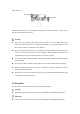
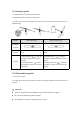
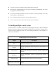
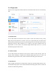

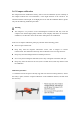
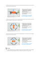
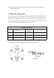
Table Of Contents
- User Manual
- EVO Lite Series
- Terms for Usage
- Trademark Information
- Copyright
- Disclaimer
- Data Storage and Use
- Table of contents
- Chapter 1 Read Instructions
- Chapter 2 Aircraft
- ① Propeller
- ④ Gimbal camera
- ② Undercarriage
- ⑤ Front LED indicator
- ③ Forward visual system
- ⑥ Motor
- ⑦ Power button
- ⑨ Rear LED indicator
- ⑧ Rear vision system
- ⑩ Air outlet
- ⑪ SD card slot
- ⑫ Aircraft battery
- ⑬ USB-C port
- ⑭ Ultrasonic sensor
- ⑯ Downward vision system
- ⑮ Downward LED
- The aircraft has one LED indicator at the end of e
- Designated symbol of color:
- R - Red
- Y - Yellow
- G - Green
- B - Blue
- Front LED Indicator
- Back LED Indicator
- Meaning
- B - Normally on
- G - Slow flash(2 secs/1 time)
- Aircraft in GPS mode
- B - Normally on
- Y - Slow flash(1 sec/1 time)
- Aircraft in ATTI mode
- B - Normally on
- Y - Slow flash(1 sec/1 time)
- Low battery warning
- B - Normally on
- R - Slow flash(1 sec/1 time)
- Serious low battery warning
- B - Normally on
- Y - Normally on
- Aircraft under calibration
- B - Normally on
- G - Normally on
- Calibration successful
- B - Normally on
- Y - Normally on
- Calibration failed
- B - Rapid flash
- G - Rapid flash
- Aircraft under pairing
- B - Rapid flash
- G - Normally on 5S
- Pairing successful
- B - Rapid flash
- R - Normally on 5S
- Pairing failed
- B - Rapid flash
- G - Rapid flash
- Aircraft under upgrading
- B - Normally on
- G - Normally on
- Upgrading successful
- B - Normally on
- Y - Slow flash(1 sec/1 time)
- Upgrading failed
- The battery for EVO Lite is 6175mAh and has the ra
- The battery indicator is divided into LED 1, LED
- Chapter 3 Remote controller
- Chapter 4 Autel Sky App
- When shooting night scene videos, users can choose
- Standard: The shooting effect is the same as the n
- Night: it will automatically adjust the ISO value,
- Super Night: it will automatically adjust the ISO
- Chapter 5 Flight
- 1) As shown in figure, press the left and right st
- 2) Slowly push up the left stick.
- 1) Press and slide the one-click takeoff button (
- 2) The aircraft will automatically rise to the hei
- Class I: main airport & low-altitude area for mann
- Class II: Sensitive area or organization & militar
- Chapter 6 Maintenance and service
- Chapter 7 Technical Specification

2.5.1 Install propeller
1. Confirm that the aircraft has been turned off.
2. Select the propeller matched for each motor.
3. Forcibly press down the propeller and rotate it along the locking direction till that it is
installed firmly.
Propeller
With white mark
Without white mark
Schematic
diagram
Installation
position
Installed to the mount with white
mark
Installed to the mount without white
mark
Legend
Locking direction ( ): rotate the
propeller to tighten it as shown in
the figure.
Unlocking direction ( ): rotate
the propeller to remove it as shown
in the figure.
Locking direction ( ): rotate the
propeller to tighten it as shown in the
figure.
Unlocking direction ( ): rotate the
propeller to remove it as shown in the
figure.
2.5.2 Disassemble propeller
1. Turn off the aircraft.
2. Forcibly press down the propeller and rotate it along the unlocking direction till that it is
removed.
Important
Check to confirm that each propeller has been installed firmly before flight.
Do not use the damaged propeller for flight.
It is forbidden to touch the rotating propeller or motor.