
Users Manual Part 1


4
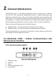
Figure 2-6 VCMI Front View
6. Power LED – refer to Table 2-4 Power LED Description for details
7. Battery LED - refer to Table 2-5 Battery LED Description for details
8. Signal Generator LED - lights green when operating in the signal generator mode
9. Multimeter LED - lights green when operating in the multimeter mode
10. Oscilloscope LED - lights green when operating in the oscilloscope mode and
flashes green when communicating
11. Vehicle LED - refer to Table 2-6 Vehicle LED Description for details
IMPORTANT
Do not disconnect the programming device while the vehicle LED status light is on! If
the flash programming procedure is interrupted while the vehicle’s ECU is blank or only
partially programmed, the module may be unrecoverable.
Figure 2-7 VCMI Bottom View
12. Ethernet Port
13. Vehicle Data Connector (DB26-Pin)
14. Input Channel A
15. Input Channel B
16. Input Channel C
17. Input Channel D