OBD-II Code Reader USER’S MANUAL AL309 www.Autel.
MS309 Manual_V1.01.fm Page 1 Wednesday, January 7, 2009 2:42 PM Table of Contents 1. Safety Precautions and Warnings . . . . . . . . . . . . . . . . . . . . . . . . . . . . . 2 1.1 Start-up Screen . . . . . . . . . . . . . . . . . . . . . . . . . . . . . . . . . . . . . . . 3 2. General Information . . . . . . . . . . . . . . . . . . . . . . . . . . . . . . . . . . . . . . . . 3 2.1 On-Board Diagnostics (OBD) II . . . . . . . . . . . . . . . . . . . . . . . . . . 3 2.2 Diagnostic Trouble Codes (DTCs) . . .
MS309 Manual_V1.01.fm Page 2 Wednesday, January 7, 2009 2:42 PM 1. Safety Precautions and Warnings To prevent personal injury or damage to vehicles and/or the code reader, read this instruction manual first and observe the following safety precautions at a minimum whenever working on a vehicle: • Always perform automotive testing in a safe environment. • Wear safety eye protection that meets ANSI standards. • Keep clothing, hair, hands, tools, test equipment, etc. away from all moving or hot engine parts.
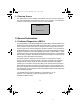
MS309 Manual_V1.01.fm Page 3 Wednesday, January 7, 2009 2:42 PM 1.1 Start-up Screen This initial start-up screen appears momentarily when the tool is first plugged in. The lower identification line reveals the version of the software. Use this version number to verify that the tool has the most up to date software. AutoLink® AL309 V. 1.17 2. General Information 2.
MS309 Manual_V1.01.fm Page 4 Wednesday, January 7, 2009 2:42 PM 2.2 Diagnostic Trouble Codes (DTCs) OBD II Diagnostic Trouble Codes are codes that are stored by the on-board computer diagnostic system in response to a problem found in the vehicle. These codes identify a particular problem area and are intended to provide you with a guide as to where a fault might be occurring within a vehicle. OBD II Diagnostic Trouble Codes consist of a five-digit alphanumeric code.
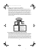
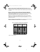
MS309 Manual_V1.01.fm Page 5 Wednesday, January 7, 2009 2:42 PM connector. If the DLC cannot be found, refer to the vehicle’s service manual for the location. Figure 1-1: The DLC connector (left) can be found in the area of the car interior seen at right (black arrow). 2.4 OBD II Readiness Monitors An important part of a vehicle’s OBD II system are the Readiness Monitors, which are indicators used to find out if all of the emissions components have been evaluated by the OBD II system.
MS309 Manual_V1.01.fm Page 6 Wednesday, January 7, 2009 2:42 PM drive etc.) before the monitor is ready to be tested. These monitors are termed non-continuous monitors and are listed below: 1. EGR System - Exhaust Gas Recirculation for reducing greenhouse gases. 2. O2 Sensors - Used to monitor and adjust air/fuel mixture. 3. Catalyst - Used to reduce exhaust emissions. 4. Evaporative System - Used to monitor the integrity of fuel tank system. 5.
MS309 Manual_V1.01.fm Page 7 Wednesday, January 7, 2009 2:42 PM 2.6 OBD II Definitions Powertrain Control Module (PCM) -- OBD II terminology for the on-board computer that controls the engine and the drive train. Malfunction Indicator Light (MIL) -- Malfunction Indicator Light (Service Engine Soon, Check Engine) is a term used for the light on the instrument panel.
MS309 Manual_V1.01.fm Page 8 Wednesday, January 7, 2009 2:42 PM 2.7 OBD II Modes of Operation Here is a basic introduction to the OBD II communication protocol. Mode byte: The first byte in the stream is the mode number. There are 9 modes for diagnostic requests, so this first byte is from 1 to 9. The first byte in the response data bytes is this same number plus 64. For example, a mode 1 request would have the first data byte = 1, and the response would have the first data byte = 65.
MS309 Manual_V1.01.fm Page 9 Wednesday, January 7, 2009 2:42 PM Mode $06 - Non-Continuously Monitored Systems test results. There are typically a minimum value, a maximum value, and a current value for each noncontinuous monitor. This data is optional, and it is defined by a given vehicle maker if it’s used. Mode $07 - Request for DTCs (pending) from Continuously Monitored Systems after a single driving cycle has been performed to determine if repair has fixed a problem.
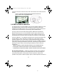
MS309 Manual_V1.01.fm Page 10 Wednesday, January 7, 2009 2:42 PM 3. Using the Code Reader 3.1 Tool Description - AL 309 1 2 4 3 5 1. OBD II CONNECTOR -- Connects the code reader to the vehicle’s Data Link Connector (DLC). 2. LCD DISPLAY -- Indicates test results. 3. ENTER/EXIT BUTTON -- Confirms a selection (or action) from a menu list, or returns to previous menu. 4. SCROLL BUTTON -- Scrolls through menu items. It is also used to enter the system setup menu when pressed. 5.
MS309 Manual_V1.01.fm Page 11 Wednesday, January 7, 2009 2:42 PM 3.2 Specifications 1) Display: Backlit, 128 x 64 pixel display 2) Operating Temperature: 0 to 60°C (32 to 140 F°) 3) Storage Temperature: -20 to 70°C (-4 to 158 F°) 4) Power: 8 to 18 Volts provided via vehicle battery 5) Dimensions: Length Width Height 110.3 mm (4.34”) 69.5 mm (2.74”) 20.2 mm (0.80”) 6) 0.18Kg (0.39lb), GW: 0.21Kg (0.46lb) 3.3 Accessories Included 1) User’s Manual -- Instructions on tool operations.
MS309 Manual_V1.01.fm Page 12 Wednesday, January 7, 2009 2:42 PM • The Settings will remain until changes to the existing settings are made. To enter the setup menu From the second startup screen, press SCROLL button to enter System Setup menu. Follow the instructions to make adjustments and settings as described in the following setup options. • The number “1/4” to the upper right corner of the screen indicates total number of items under the menu and sequence of currently selected item.
MS309 Manual_V1.01.fm Page 13 Wednesday, January 7, 2009 2:42 PM Unit of Measurement • Metric is the default measurement unit. 1) From System Setup menu, use SCROLL button to select Unit of Measure and press ENTER/EXIT button. 2) From Unit of Measure menu, use SCROLL button to select the desired unit of measurement. 3) Press ENTER/EXIT button to save your selection and return to previous menu.
MS309 Manual_V1.01.fm Page 14 Wednesday, January 7, 2009 2:42 PM 3) Press ENTER/EXIT button to save your settings and return to previous menu. Exiting System Setup 1) Use SCROLL button to select Exit and press ENTER/EXIT button to return to startup menu. 3.7 Vehicle Coverage The AutoLink TM AL309 OBD II/EOBD Code Reader is specially designed to work with all OBD II compliant vehicles, including those equipped with the nextgeneration protocol -- Control Area Network (CAN).
MS309 Manual_V1.01.fm Page 15 Wednesday, January 7, 2009 2:42 PM CAUTION: Don’t connect or disconnect any test equipment with the ignition on, or with the engine running. 1) Turn the engine off. 2) Locate the vehicle’s 16-pin Data Link Connector (DLC). 3) Plug into the OBDII cable to the vehicle’s DLC. 4) Turn the ignition on. Engine can be off or running. 5) Press ENTER/EXIT button to enter Diagnostic Menu.
MS309 Manual_V1.01.fm Page 16 Wednesday, January 7, 2009 2:42 PM 4.1 System Status .............Diagnostic Menu....... ... 1/8 1) System Status 2) Read Codes 3) Erase Codes 4) Live Data Press ENTER to select #1 System Status, the following screen will be displayed if there is only one control module. Press SCROLL to exit System Status and return to the main Diagnostic Menu. …………….
MS309 Manual_V1.01.fm Page 17 Wednesday, January 7, 2009 2:42 PM 4.2 Reading Codes 1) Use SCROLL button to select Read Codes from Diagnostic Menu and press ENTER/EXIT button. .............Diagnostic Menu....... ... 2/8 1) System Status 2) Read Codes 3) Erase Codes 4) Live Data diagnostic menu continued... ............Diagnostic Menu......... .. 5) View Freeze Frame 6) I/M Readiness 7) Vehicle Info. 8) Exit • If more than one module is detected, you will be prompted to select a module before test.
MS309 Manual_V1.01.fm Page 18 Wednesday, January 7, 2009 2:42 PM 3) If more than one DTC is found, use SCROLL button, as necessary, until all the codes have been shown up. • If no codes are detected, a “No codes are stored in the module!” message displays on the screen.
MS309 Manual_V1.01.fm Page 19 Wednesday, January 7, 2009 2:42 PM diagnostic menu continued... . ...... .....D ia g no stic Menu ..... .... . . 5) 6) 7) 8) V iew Freez e Fram e I/M Readines s V ehicle Info. E xit 2) A warning message comes up asking for your confirmation. 3) If you want to proceed with erasing the codes, press the ENTER/EXIT button to erase. • If the codes are cleared successfully, an “Erase Done!” message shows up. • If the codes are not cleared, then an “Erase Failure.
MS309 Manual_V1.01.fm Page 20 Wednesday, January 7, 2009 2:42 PM The AL 309 allows you to see the same data used by the vehicle's computer to make calculations necessary for conducting corrections and adjustments to particular vehicle systems. PIDs have specific operating characteristics that identify them. The AL 309 provides PIDs for each module being tested. 1) To view live data, use scroll button to select Live Data from Diagnostic Menu and press ENTER button. .............Diagnostic Menu....... ...
MS309 Manual_V1.01.fm Page 21 Wednesday, January 7, 2009 2:42 PM 4.5 Viewing Freeze Frame Data Freeze Frame Data allows the technician to view the vehicle’s operating parameters at the moment a DTC (Diagnostic Trouble Code) is detected. For example, the parameters may include engine speed (RPM), engine coolant temperature (ETC), or vehicle speed sensor (VSS) etc. This information will aid the technician by allowing the parameters to be duplicated for diagnostic and repair purposes.
MS309 Manual_V1.01.fm Page 22 Wednesday, January 7, 2009 2:42 PM 3) The retrieved information covers more than one screen. Use the SCROLL button, as necessary, until all data have been viewed. • The number “1/4” in the upper right corner indicates the total number of screens that will display the retrieved freeze frame data in this case, we are on page one of four. • If there is no freeze frame data available, an advisory message “No Freeze Frame Data Stored!” shows on the display.
MS309 Manual_V1.01.fm Page 23 Wednesday, January 7, 2009 2:42 PM 1) Use SCROLL button to select I/M Readiness from Diagnostic Menu and press ENTER/EXIT. ............Diagnostic Menu......... .. 6/8 5) View Freeze Frame 6) I/M Readiness 7) Vehicle Info. 8) Exit • If more than one module is detected, you will be prompted to select a module before test. Transmission • Use the SCROLL button to select a module and then press the ENTER/EXIT button.
MS309 Manual_V1.01.fm Page 24 Wednesday, January 7, 2009 2:42 PM 4) Use SCROLL button to view the status of the MIL light (“ON” or “OFF) and the following monitors: (these monitors are for emissions sytems) • Misfire monitor -- Misfire monitor • Fuel System Mon. -- Fuel System Monitor • Comp. Component -- Comprehensive Components Monitor • EGR - Exhaust Gas Recirculation System Monitor • Oxygen Sens. Mon. -- O2 Sensors Monitor • Catalyst Mon. -- Catalyst Monitor • EVAP System Mon.
MS309 Manual_V1.01.fm Page 25 Wednesday, January 7, 2009 2:42 PM 4.7 Viewing Vehicle Information The Vehicle Info. function enables retrieval of the Vehicle Identification No. (VIN), Calibration ID(s), Calibration Verification Nos. (CVNs) and In-use Performance Tracking on 2000 and newer vehicles that support Mode 9. 1) Use SCROLL button to select Vehicle Info. from Diagnostic Menu and press ENTER/EXIT button. ............D ia gno stic Menu......... ..
MS309 Manual_V1.01.fm Page 26 Wednesday, January 7, 2009 2:42 PM 3) Wait a few seconds while the code reader reads vehicle information. 4) From Vehicle Info. menu, use SCROLL button to select an available items to view and press ENTER/EXIT button. 5) View retrieved vehicle information on the screen. 6) Press ENTER/EXIT to return to previous menu. 4.8 Exiting the OBDII Test 1) To exit OBDII test, use SCROLL button to select Exit from Diagnostic Menu and press ENTER/EXIT button. ............
MS309 Manual_V1.01.fm Page 27 Wednesday, January 7, 2009 2:42 PM 2) A warning message comes up asking your confirmation. 3) If you do want to exit OBDII test, press ENTER/EXIT button. • If you do not want to exit, use the SCROLL button the select NO and press the ENTER/EXIT button to return.
MS309 Manual_V1.01.fm Page 28 Wednesday, January 7, 2009 2:42 PM 5. Warranty and Service 5.
MS309 Manual_V1.01.
MS309 Manual_V1.01.
Autel.us / Autel Intelligent Technology Co., Ltd. www.autel.us All Rights Reserved. V. 1.