Trademarks Autel®, MaxiSys®, MaxiDAS®, MaxiScan®, MaxiCheck®, MaxiRecorder®, and MaxiCheck® are trademarks of Autel Intelligent Technology Corp., Ltd., registered in China, the United States and other countries. All other marks are trademarks or registered trademarks of their respective holders.
Safety Information For your own safety and the safety of others, and to prevent damage to the device and vehicles upon which it is used, it is important that the safety instructions presented throughout this manual be read and understood by all persons operating or coming into contact with the device. There are various procedures, techniques, tools, and parts for servicing vehicles, as well as in the skill of the person doing the work.
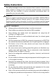
Safety Instructions The safety messages herein cover situations Autel is aware of. Autel cannot know, evaluate or advise you as to all of the possible hazards. You must be certain that any condition or service procedure encountered does not jeopardize your personal safety. DANGER When an engine is operating, keep the service area WELL VENTILATED or attach a building exhaust removal system to the engine exhaust system.
personal injury or damage to the test equipment. To avoid damaging the test equipment or generating false data, make sure the vehicle battery is fully charged and the connection to the vehicle DLC is clean and secure. Do not place the test equipment on the distributor of the vehicle. Strong electro-magnetic interference can damage the equipment.
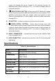
CONTENTS USING THIS MANUAL ........................................................................... 1 CONVENTIONS ........................................................................................... 1 USING THE SCAN TOOL ....................................................................... 3 TOOL DESCRIPTION .................................................................................... 3 SPECIFICATIONS ........................................................................................
SRS ...................................................................................................... 36 READ CODES ........................................................................................... 36 ERASE CODES ......................................................................................... 36 DTC LOOKUP....................................................................................... 38 PLAYBACK DATA ............................................................................
Using This Manual This manual contains device usage instructions. Some illustrations shown in this manual may contain modules and optional equipment that are not included in your system. Contact your sales representative for availability of other modules and optional tools or accessories. Conventions The following conventions are used. Bold Text Bold text is used to highlight selectable items such as buttons and menu options. Example: Tap OK.
IMPORTANT Keep the cable away from heat, oil, sharp edges and moving parts. Replace damaged cables immediately. Hyperlink Hyperlinks, or links, that take you to other related articles, procedures, and illustrations are available in electronic documents. Blue italic text indicates a selectable hyperlink and blue underlined text indicates a website link or an email address link. Illustrations Illustrations used in this manual are samples, the actual testing screen may vary by test vehicle.
Using the Scan Tool Tool Description Figure 2-1 Scan Tool View 1) LCD DISPLAY –displays menus and test results. 2) FUNCTION BUTTONS – corresponds with “buttons” on screen for executing commands. 3) HELP BUTTON – provides help information and Code Breaker function. 4) ESC BUTTON – cancels a selection (or an action) from a menu or returns to the previous screen.
moves up through the current screen to the previous screens for additional data. When looking up DTC, it is used to change value of selected character. 7) RIGHT SCROLL BUTTON – When look up DTC definitions, moves to next character and view additional information on next screens if DTC definition covers more than one screen; views next screen or next frames of recorded data. It is also used to view next trouble code when viewing DTCs. 8) OK BUTTON – confirms a selection (or action) from a menu.
Accessories Included 1) OBDII Cable – provides power to tool and communicates between tool and vehicle. 2) USB Cable – used to upgrade the scan tool and to print retrieved data. 3) User Manual – instructions on tool operations. 4) Quick Guide – instructions on device connection and tool registration and update. Keypad No solvents such as alcohol are allowed to clean the keypad or display. Use a mild nonabrasive detergent and a soft cotton cloth. Do not soak the keypad as it is not waterproof.
Vehicle Coverage The AutoLink AL609P OBDII Scanner is specially designed to work with all OBD II compliant vehicles, including those equipped with next-generation protocol -- Control Area Network (CAN). It is required by EPA that all 1996 and newer vehicles (cars and light trucks) sold in the United States must be OBD II compliant and this includes all Domestic, Asian and European vehicles. A small number of 1994 and 1995 model year gasoline vehicles are OBD II compliant.
Verify that the ignition is ON. Check if the scan tool’s OBD connected to the vehicle’s DLC. Verify that the vehicle is OBDII compliant. Turn the ignition off and wait for about 10 seconds. Turn the ignition back to on and continue the testing. Verify the control module is not defective. II connector is securely Operating Error If the scan tool freezes, then an exception occurs or the vehicle’s ECU (Engine Control Unit) is too slow to respond to requests.
OBD II Diagnostics When more than one vehicle control module is detected by the scan tool, you will be prompted to select the module where the data may be retrieved. The most often to be selected are the Power train Control Module [PCM] and Transmission Control Module [TCM]. CAUTION: Don’t connect or disconnect any test equipment with ignition on or engine running. 1) Turn the ignition off. 2) Locate the vehicle’s 16-pin Data Link Connector (DLC).
Verify that the vehicle is OBD II compliant; Turn the ignition off and wait for about 10 seconds. Turn the ignition back to on and repeat the procedure from step 5. If the “LINKING ERROR” message does not go away, then there might be problems for the scan tool to communicate with the vehicle. Contact your local distributor or the manufacturer’s customer service department for assistance. 7) View a summary of system status (MIL status, DTC counts, Monitor status) on screen.
9) If you wish to erase the data, press the OK button; if you do not want to erase the data, press ESC to exit or use LEFT/RIGHT button to select NO and press OK for Diagnostic Menu to come up. Read Codes Read Codes can be done with the key on engine off (KOEO) or with the key on engine running (KOER).
Figure 3-5 Sample Read Codes Screen The OBD Codes reads pending codes, stored codes, and permanent codes. The Enhanced Codes reads DTCs from engine and transmission systems of GM, Chrysler, and Ford vehicles. If there is not any Diagnostic Trouble Code, the display indicates “No (pending) codes are stored in the module!” Wait a few seconds or press any key to return to previous screen. NOTE Permanent Codes function is available for merely vehicles supporting the CAN protocols.
1. Erasing the Diagnostic Trouble Codes may allow the scan tool to delete not only the codes from the vehicle’s on-board computer, but also “Freeze Frame” data and manufacturer specific enhanced data. Further, the I/M Readiness Monitor Status for all vehicle monitors is reset to Not Ready or Not Complete status. Do not erase the codes before the system has been checked completely by a technician. 2. Erasing codes does not mean that trouble codes in ECU have been eliminated completely.
In this function, you can not only read the live data but also record data for later review. View Data The View Data function allows viewing of live or real time PID data of vehicle’s computer module(s). 1) To view live data, use the UP/DOWN scroll button to select Live Data from Diagnostic Menu and press the OK button. 2) Wait a few seconds while the scan tool validates the PID MAP.
Figure 3-10 Sample View Data Menu 2) View live PIDs on the screen. Use the UP/DOWN scroll button for more PIDs if additional information is available on more than one page. Figure 3-11 Sample Complete Data Screen The number “x” to the right of the screen indicates sequence of the highlighted item. To view full name of the highlighted PID, press the “?” button. If the G icon appears when a PID is highlighted, graphic information is available. Press OK to view graph.
3) Press the ESC button to return to previous menu. View Custom Data Set 1) To view customized PID data, use the UP/DOWN scroll button to select Custom Data Set from View Data menu and press the OK button. 2) Observe on-screen instructions. Figure 3-13 Sample Custom Data Set Screen 1 3) Use the RIGHT button to deselect/select data parameters, and use the UP/DOWN scroll button to move up and down. Selected parameters are marked with solid squares.
Figure 3-15 Sample Custom Data Set Screen 3 5) Use the ESC button to return to previous menu. Record Data The Record Data function allows recording vehicle modules’ Parameter Identification (PID) data to help diagnose intermittent vehicle problems. A recording includes 5 frames of live data before trigger event and several frames after trigger event. There are two trigger modes used to record data: A. Manual Trigger – allows user to press the OK button to start recording. B.
Figure 3-16 Sample Record Data Screen 2) Use the UP/DOWN scroll button to select a trigger mode and press the OK button. Figure 3-17 Sample Pick Trigger Mode Screen 3) If data from previously tested vehicle is not erased, data from current test will be stored in a temporary cache. Use the UP/DOWN scroll button to select a memory location and press the OK button.
Figure 3-19 Sample Select Memory Screen 4) If you wish to proceed with overwriting the old recording, press the OK button; if you do not wish to overwrite it, use the LEFT/RIGHT button to select NO or press the ESC button to pick another memory location. Observe on-screen instructions.
Drive till a DTC is detected when DTC Trigger is selected. If no DTCs are detected, press ESC to exit recording. Figure 3-22 Sample Recording Data Screen 6) The number “x/x...” to the upper right corner of the screen indicates the maximum frames that can be recorded and the number of recorded frames. The scan tool keeps recording PID data until user presses the ESC button, selected memory location is full, or it completes recording. A message prompting to playback data shows on the screen.
3) 4) Use the RIGHT button select/deselect data parameters. Selected parameters are marked with solid squares. Press the OK button to confirm. If you wish to deselect all marked items, press LEFT button. A message comes up to ask for your confirmation. If you decide to deselect these items, press OK; if you decide not to, press the ESC button, or use the UP/DOWN button to select NO and press OK to continue PID selections.
Figure 3-24 Sample Select Memory Screen 2 3) If there is no recording in selected location, a message “Not Supported or Stored No Data” displays on the screen. Use the UP/DOWN button to view recorded PIDs of each frame. Figure 3-25 Sample Playback Data Screen 4) Use the LEFT/RIGHT button to view PIDs of next or previous frames. View Freeze Frame Data Freeze Frame Data allows the technician to view the vehicle’s operating parameters at the moment a DTC (Diagnostic Trouble Code) is detected.
Figure 3-26 Sample View Freeze Frame Screen If there is no freeze frame data available, an advisory message “No freeze frame data stored!” shows on the display. 4) If you want to view full name of a PID, use the UP/DOWN scroll button to select the PID, and press the HELP button. 5) Press ESC button to return to previous screen. Retrieve I/M Readiness Status I/M Readiness function is used to check the operations of the Emission System on OBD II compliant vehicles.
Retrieve I/M Readiness status in typical way 1) Use the UP/DOWN scroll button to select I/M Readiness from Diagnostic Menu and press OK button. 2) Wait a few seconds while the scan tool validates the PID MAP. 3) If the vehicle supports both types of tests, then both types will be shown on the screen for selection. Figure 3-27 Sample I/M Readiness Selection Screen 4) Use the UP/DOWN scroll button, as necessary, to view the status of the MIL light (ON or OFF) and the following monitors.
HCCAT – NMHC Catalyst Monitor NCAT – NOx Aftertreatment Monitor BP – Boost Pressure System Monitor EGS – Exhaust Gas Sensor Monitor PM – PM Filter Monitor 5) If the vehicle supports readiness test of “This Drive Cycle”, a screen of the following displays. 6) Use the UP/DOWN scroll button for more PIDs if additional information is available on more than one page. Or use the LEFT/RIGHT scroll button to view PIDs in the previous/next page.
specified limits. These test results are saved in the on-board computer's memory. The O2 Monitor Test function allows retrieval and viewing of O2 sensor monitor test results for the most recently performed tests from the vehicle's on-board computer. The O2 Monitor Test function is not supported by vehicles which communicate using a controller area network (CAN). For O2 Monitor Test results of CAN-equipped vehicles, see On-Board Monitor Test on page 26.
6) Press the ESC button to return to the previous menu. On-Board Monitor Test The On-Board Monitor Test is useful after servicing or after erasing a vehicle’s control module memory. The On-Board Monitor Test for non-CAN-equipped vehicles retrieves and displays test results for emission-related power train components and systems that are not continuously monitored.
Figure 3-32 Sample On-board Mon. Test Screen 1 5) From On-Board Mon. Test menu, use the UP/DOWN scroll button to select a test to view and press the OK button. Or, use the LEFT/RIGHT scroll button to view previous/next screen of test items. If the vehicle under test does not support the mode, an advisory message will be displayed on the screen. For CAN-equipped vehicles, test selections can be as below: Figure 3-33 Sample On-board Mon.
NOTE If the On-Board Monitor Test failed, this monitor item will be red color. Just by the text color you may easily find out which system is at fault. Figure 3-35 Sample On-board Mon. Test Screen 4 8) Press ESC button to return to the previous menus. Component Test The Component Test function allows initiating a leak test for the vehicle's EVAP system. The scan tool itself does not perform the leak test, but commands the vehicle's on-board computer to start the test.
Figure 3-37 Sample Component Test Screen 2 Some vehicles do not allow scan tools to control vehicle systems or components. If the vehicle under test does not support the EVAP Leak Test, an advisory message is displayed on the screen. Figure 3-38 Sample Component Test Screen 3 4) Wait a few seconds or press any key to return to previous screen. View Vehicle Information The Vehicle Info. function enables retrieval of Vehicle Identification No. (VIN), Calibration ID Nos.
Figure 3-39 Sample Vehicle Info. Screen 1 3) Wait a few seconds while the scan tool reads vehicle information. 4) If the vehicle does not support this mode, a message shows on the display warning that the mode is not supported. From Vehicle Info. Menu, use the UP/DOWN scroll button to select an available item to view and press the OK button. Figure 3-40 Sample Vehicle Info. Screen 2 1) View retrieved vehicle information on screen. Figure 3-41 Sample Vehicle Info.
Modules Present The Modules Present function allows viewing of the module IDs and communication protocols for OBD2 modules in the vehicle. 1) Use the UP/DOWN scroll button to select Modules Present from Diagnostic Menu and press OK button. 2) View modules present with their IDs and communication protocols. Figure 3-42 Sample Modules Present Screen 3) Press the ESC button to return to previous menu.
Figure 3-44 Sample Code Breaker Screen 3) Click on System Description and Quick Check to read the code information, symptoms, specifications, data/sensor information, etc. 4) Click on General Notes to view helpful repair information of DTCs. 5) To return to previous screen, press ESC button.
ABS An anti-lock braking system (ABS) is an automobile safety system that allows the wheels on a motor vehicle to maintain tractive contact with the road surface according to driver inputs while braking, preventing the wheels from locking up (ceasing rotation) and avoiding uncontrolled skidding. It is an automated system that uses the principles of threshold braking and cadence braking which were practiced by skillful drivers with previous generation braking systems.
Figure 4-2 Sample Trouble Codes Screen 3. All the DTCs of the ABS control module are displayed. The data will be automatically saved for later review. Erase Codes 1. Select Erase codes from the diagnostic function list (Figure 4-1). 2. Follow the on-screen instruction and make sure the ignition on and engine off. Press Yes to continue. Figure 4-3 Sample Erase Codes Screen 3. A confirmation message “DTCs and freeze data will be deleted.
Figure 4-4 Sample Erase Codes Screen NOTE For some test vehicles, the Erase Codes function is automatically performed after Read Codes function, follow the on-screen instructions to complete the service.
SRS The purpose of the SRS light on your instrument panel is to alert you of a potential problem with your supplemental restraint system. Use the AL609P to have the system checked if: The light does not come on when you turn the ignition ON. The light stays on after the engine starts. The light comes on or flashes while you are driving. Read Codes 1. From Main Screen (Figure 2-2), use the UP/DOWN scroll button and LEFT/RIGHT scroll button to select SRS and press the OK button. 2.
Press Yes to continue. 4. Erase Codes command will be sent and you can perform Read Codes function to verify. Press any key to continue.
DTC Lookup The DTC Lookup function allows user to search definitions of DTC stored in built-in DTC library. 1) From Main Screen (Figure 2-2), use the UP/DOWN scroll button and LEFT/RIGHT scroll button to select DTC Lookup and press the OK button. 2) From DTC Lookup screen, use the LEFT/RIGHT button to move to the desired character, use the UP/DOWN button to change selected digit/character and press the OK button to confirm. Figure 6-1 Sample DTC Lookup Screen 3) View the DTC definition on screen.
4) To view previous or next DTC in the built-in DTC library, use the LEFT/RIGHT button. 5) To enter another DTC, press the ESC button to return to previous screen. 6) To exit to Main Screen, press the ESC button.
Playback Data The Playback function allows viewing and printing of data from last test recorded by the scan tool. Review Data 1) Use the LEFT/RIGHT scroll button to select Playback from Main Screen (Figure 2-2), and press the OK button. Wait for the Review Data screen to appear. Figure 7-1 Sample Review Data Screen 1 2) To review data saved in the OBDII/EOBD function, select OBDII/EOBD in the Replay menu. To review data saved in the ABS/SRS function, select ABS/SRS in the Replay menu.
Figure 7-2 Sample Review Data Screen 2 If no data from previously tested vehicle is recorded, a message “No data available!” shows on the screen. Review selected data on screen. Figure 7-3 Sample Reviewing Data Screen 3 Delete Data By selecting Delete on the review screen (Figure 7-1), you are allowed to erase the selected data on the scan tool. Review the recordings thoroughly before erasing. You could also erase all recordings by select Delete All.
The Print Data function allows printing out DTC data recorded by the scan tool by connecting the scan tool to a PC or laptop with the USB cable supplied. 1) Download the Maxi PC Suite from www.autel.com and install. 2) Connect the scanner to computer with the USB cable supplied. 3) Run Autel Printer software on computer. 4) Select Playback function in Main Screen of the scan tool. In Scan/OBDII screen, use the UP/DOWN scroll button to select the data you want to print.
NOTE The scan tool can only print text data even though the data is saved in graphic mode. The print function is not available on Mac for the present.
System Setup The System Setup functions allow you to adjust default settings and view information about the scan tool. 1) Language: Selects the desired language. 2) Unit of Measure: Sets the unit of measure to English or Metric. 3) Key Beep Set: Turns on/off beep. 4) About: Provides information of the scan tool. 5) Tool Self-test: Checks if the LCD display and keyboard are working normally. 6) Update Mode: Accesses the Update Mode.
1) From System Setup screen, use the UP/DOWN scroll button to select Language, and press the OK button. 2) Use the UP/DOWN scroll button to select the desired language and press the OK button to save your selection and return to previous screen. Figure 8-2 Sample Language Screen Unit of Measure Metric is the default measurement unit. 1) From System Setup screen, use the UP/DOWN scroll button to select Unit of Measure and press the OK button.
Key Beep Set This function allows you to turn on/off the build-in speaker for key pressing. The default setting is Beep On. 1) From System Setup screen, use the UP/DOWN scroll button to select Key Beep Set and press the OK button. 2) From Key Beep Set menu, use the UP/DOWN scroll button to select Beep ON or Beep OFF to turn on/off the beep. Figure 8-4 Sample Key Beep Set Screen 3) Press the OK button to save your selection and return to previous menu.
Figure 8-5 Sample About Screen Tool Self-test The Tool Self-test function checks if the display and keyboard are working properly. Display test The Display Test function checks if the LCD display is working normally. 1) From System Setup screen, use the UP/DOWN scroll button to select Tool Self-test, and press the OK button. 2) Select Display Test from Tool Self-test menu and press the OK button to start test. 3) Look for missing spots in the red, green, blue, black and white LCD display.
Keyboard Test The Keyboard Test function verifies if the keys are functioning properly. 1) Use the UP/DOWN scroll button to select Keyboard Test from the Tool Self-test menu (Figure 8-6), and then press the OK button. 2) Press any key to start test. When you press a key, the key name should be observed on the display. If the key name does not show up, then the key is not functioning properly. 3) Double press ESC to return to previous menu.
2. If you already have an Autel account, Sign In with your account ID and password. 3. If you are a new member to Autel, click on the Create Autel ID button on the left side to create an ID. 4. Enter the required information in the input fields, and click the Get Verification Code button to get a verification code for email validation. 5. The online system will automatically send a verification code to the registered email address.
Figure 8-8 Sample Log in Window 3. Connect the scan tool to your computer through the USB cable provided. 4. From System Setup screen in scan tool, select Update Mode, and press the OK button. 5. Enter your Autel ID and password and wait for the Update window to display. If you forget your password, you may click the [Forget Password?] to link to our website and find your password back. Or you may click Sign up to create an Autel ID to continue. 6.
bottom of screen Click the Clear All button will reselect the items you want to update. 2. Or, click on the Select All checkbox on the left bottom of screen and all updatable items will be selected automatically. Then click the Update All button on the right side of screen. 3. When the downloading is completed, the downloaded programs will be installed automatically. The new version will replace the old version. Single Update 1.
Compliance Information FCC Compliance This device complies with Part 15 of the FCC rules and Industry Canada’s license-exempt RSSs. Operation is subject to the following two conditions: 1. This device may not cause harmful interference. 2. This device must accept any interference received, including interference that may cause undesired operation. Cet appareil est conforme aux CNR exempts de licence d’Industrie Canada. Son fonctionnement est soumis aux deux conditions suivantes: 1.
-- Connect the equipment into an outlet on a circuit different from that to which the receiver is connected. -- Consult the dealer or an experienced radio/TV technician for help. Changes or modifications not expressly approved by the party responsible for compliance could void the user’s authority to operate the equipment. SAR The radiated output power of this device is below the FCC radio frequency exposure limits.
Warranty and Service Limited One Year Warranty Autel warrants to its customers that this product will be free from all defects in materials and workmanship for a period of one (1) year from the date of the original purchase, subject to the following terms and conditions: 1) The sole responsibility of Autel under the Warranty is limited to either the repair or, at the option of Autel, replacement of the scan tool at no charge with Proof of Purchase. The sales receipt may be used for this purpose.