
User Manual


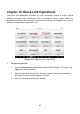


Table Of Contents
- Trademarks
- Copyright Information
- Disclaimer of Warranties and Limitation of Liabili
- For Services and Support:
- Safety Information
- Chapter 1 Using This Manual
- Chapter 2 General Introduction
- Chapter 3 Getting Started
- Chapter 4 Diagnostics Operations
- Chapter 5 Data Manager Operations
- Chapter 6 ADAS
- Chapter 7 MaxiFix Operations
- Chapter 8 Settings Operations
- Chapter 9 Shop Manager Operations
- Chapter 10 Update Operations
- Chapter 11 VCI Manager Operations
- Chapter 12 Remote Desk Operations
- Chapter 13 Support
- Chapter 14 Academy
- Chapter 15 Quick Link Operations
- Chapter 16 MaxiScope Operations
- Chapter 17 Function Viewer
- Chapter 18 Digital Inspection Operations
- Chapter 19 Maintenance and Service
- Chapter 20 Compliance Information
- Chapter 21 Warranty

103
the signal voltage, and so the more detailed will be the trace that appears on the scope
screen.
Streaming Mode
This term indicates a sampling mode in which the oscilloscope samples data and
returns it to the computer in an unbroken stream. This mode of operation is effective
when the input signal being sampled is at low frequency.
Time Base
The time base controls the time interval across the scope display.
Voltage Range
The voltage range is the range between the maximum and minimum voltages that can
be accurately captured by the oscilloscope.
Sinusoidal Waveform
This term describes the waveform characteristics typically found in circuits with large
inductance and capacitance, and often referred to as an AC signal. The waveform
alternates either side of 0 volts or may rise and fall creating a regular sinusoidal shape:
Amplitude
This term indicates the maximum voltage generated from the zero volts line of the
oscilloscope.
Figure 16- 1 Sample Sinusoidal Waveform