
User Manual


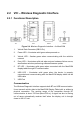


Table Of Contents
- Trademarks
- Copyright Information
- Disclaimer of Warranties and Limitation of Liabili
- For Services and Support:
- Safety Information
- Chapter 1 Using This Manual
- Chapter 2 General Introduction
- Chapter 3 Getting Started
- Chapter 4 Diagnostics Operations
- Chapter 5 Data Manager Operations
- Chapter 6 ADAS
- Chapter 7 MaxiFix Operations
- Chapter 8 Settings Operations
- Chapter 9 Shop Manager Operations
- Chapter 10 Update Operations
- Chapter 11 VCI Manager Operations
- Chapter 12 Remote Desk Operations
- Chapter 13 Support
- Chapter 14 Academy
- Chapter 15 Quick Link Operations
- Chapter 16 MaxiScope Operations
- Chapter 17 Function Viewer
- Chapter 18 Digital Inspection Operations
- Chapter 19 Maintenance and Service
- Chapter 20 Compliance Information
- Chapter 21 Warranty

8
2.2 VCI – Wireless Diagnostic Interface
2.2.1 Functional Description
Figure 2- 4 Wireless Diagnostic Interface – for MaxiCOM
1. Vehicle Data Connector (DB15-Pin)
2. Power LED – illuminates solid green when powered on
3. Vehicle LED – flashes green when communicating with the vehicle’s
network
4. Error LED – illuminates solid red when serious hardware failure occurs;
also flashes red when performing software/firmware update
5. BT LED – illuminates solid green when connected with the MaxiCOM
display tablet through BT communication
6. USB LED – illuminates solid green when the device is properly
connected and communicating with the MaxiCOM display tablet via the
USB cable
7. USB Port
Communication
The Wireless Diagnostic Interface supports both BT and USB communication.
It can transmit vehicle data to the MaxiCOM Display Tablet with or without a
physical connection. The working range of the transmitter through BT
communication is about 755 feet (about 230 m). A signal lost due to moving
out of range automatically restores itself when the display unit is brought
closer to the VCI unit.