
User Manual


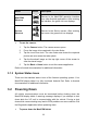


Table Of Contents
- Trademarks
- Copyright Information
- Disclaimer of Warranties and Limitation of Liabili
- For Services and Support:
- Safety Information
- Chapter 1 Using This Manual
- Chapter 2 General Introduction
- Chapter 3 Getting Started
- Chapter 4 Diagnostics Operations
- Chapter 5 Data Manager Operations
- Chapter 6 ADAS
- Chapter 7 MaxiFix Operations
- Chapter 8 Settings Operations
- Chapter 9 Shop Manager Operations
- Chapter 10 Update Operations
- Chapter 11 VCI Manager Operations
- Chapter 12 Remote Desk Operations
- Chapter 13 Support
- Chapter 14 Academy
- Chapter 15 Quick Link Operations
- Chapter 16 MaxiScope Operations
- Chapter 17 Function Viewer
- Chapter 18 Digital Inspection Operations
- Chapter 19 Maintenance and Service
- Chapter 20 Compliance Information
- Chapter 21 Warranty
22
Chapter 4 Diagnostics Operations
By establishing a data link to the electronic control systems of the vehicle being
serviced through the VCI device, the Diagnostics application allows you to retrieve
diagnostic information, view live data parameters, and perform active tests. The
Diagnostics application can access the electronic control module (ECM) for various
vehicle control systems, such as engine, transmission, antilock brake system (ABS),
airbag system (SRS) and more.
4.1 Establishing Vehicle Communication
The Diagnostics operations require connecting the MaxiCOM
MK908/MaxiCOM MK908P Diagnostic Platform to the test vehicle through the
VCI device using the main cable, and test adapters (for non-OBD II vehicles).
To establish proper vehicle communication to the MaxiCOM display tablet, you
need to perform the following steps:
1. Connect the VCI device to the vehicle’s DLC for both communication and
power source.
2. Connect the VCI device to the MaxiCOM display tablet via BT pairing, or
USB connection.
3. When these are done, check the VCI navigation button at the bottom bar
on the screen, if the button displays a green tick icon at the lower right
corner, the MaxiCOM MK908/MaxiCOM MK908P diagnostic platform is
ready to start vehicle diagnosis.
4.1.1 Vehicle Connection
The method used to connect the VCI device to a vehicle’s DLC depends on
the vehicle’s configuration as follows:
A vehicle equipped with an On-board Diagnostics Two (OBD II) management
system supplies both communication and 12-volt power through a
standardized J-1962 DLC.
A vehicle not equipped with an OBD II management system supplies
communication through a DLC connection, and in some cases supplies
12-volt power through the cigarette lighter receptacle or a connection to
the vehicle battery.