Trademarks Autel®, MaxiSys®, MaxiDAS®, MaxiScan®, MaxiTPMS®, MaxiRecorder®, and MaxiCheck® are trademarks of Autel Intelligent Technology Corp., Ltd., registered in China, the United States and other countries. All other marks are trademarks or registered trademarks of their respective holders.
Safety Information For your own safety and the safety of others, and to prevent damage to the device and vehicles upon which it is used, it is important that the safety instructions presented throughout this manual be read and understood by all persons operating or coming into contact with the device. There are various procedures, techniques, tools, and parts for servicing vehicles, as well as in the skill of the person doing the work.
carbon monoxide, an odorless, poisonous gas that causes slower reaction time and can lead to serious personal injury or loss of life. Do Not Turn the Volume Up Too Loud When Using Headphones Listening at high volumes that over-stimulate the ear for long periods of time may result in loss of hearing. SAFETY WARNINGS: ⚫ Always perform automotive testing in a safe environment. ⚫ Wear safety eye protection that meets ANSI standards. ⚫ Keep clothing, hair, hands, tools, test equipment, etc.
CONTENTS 1 USING THIS MANUAL ...................................................................................................1 CONVENTIONS ...................................................................................................................1 2 GENERAL INTRODUCTION ..........................................................................................3 MAXISYS DISPLAY TABLET .................................................................................................
8 DATA MANAGER .........................................................................................................70 OPERATIONS ................................................................................................................... 70 9 SETTINGS .................................................................................................................... 74 OPERATIONS ..................................................................................................................
1 Using This Manual This manual contains device usage instructions. Some illustrations shown in this manual may contain modules and optional equipment that are not included in your system. Conventions The following conventions are used. Bold Text Bold text is used to highlight selectable items such as buttons and menu options. Example: ⚫ Tap OK. Notes and Important Messages Notes A NOTE provides helpful information such as additional explanations, tips, and comments.
Hyperlink Hyperlinks or links that take you to other related articles, procedures, and illustrations are available in electronic documents. Blue italic text indicates a selectable hyperlink and blue underlined text indicates a website link or an email address link. Illustrations Illustrations used in this manual are samples, and the actual testing screen may vary for each vehicle being tested. Observe the menu titles and on-screen instructions to make correct option selection.
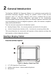
2 General Introduction The MaxiSys® MS908S Pro Diagnostic Platform is an evolutionary smart solution for specialized automotive diagnosis. Utilizing the powerful Cortex A7+A15 six-core processor, and a 9.
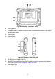
Figure 2-2 MaxiSys Tablet Back View 1. Audio Speaker 2. Collapsible Stand – extends from the back to allow hands-free viewing of the tablet at a 30 degree angle. 3. Camera Lens 4. Camera Flash Figure 2-3 MaxiSys Tablet Left Side 1. Mini SD (Secure Digital) Card Slot 2. Mini USB (Universal Serial Bus) Port (it cannot be used at the same time with the No. 4 USB Port in Figure 2-4 MaxiSys Tablet Top View) 3.
Figure 2-4 MaxiSys Tablet Top View 1. DC Power Supply Input Port 2. HDMI (High-Definition Multimedia Interface) Port 3. USB Port 4. USB Port (it cannot be used at the same time with the Mini USB Port in Figure 2-3 MaxiSys Tablet Left Side) 5. Lock/Power Button – long press to turn on and off MaxiSys, or short press to lock the screen.
Technical Specifications Table 2-1 Tablet Specifications Item Description Operating System AndroidTM 4.4.2, KitKat Processor Samsung Exynos Six-core Processor (1.3GHz Quad-core ARM Cortex-A7 + 1.7GHz Dual-core ARM Cortex-A15) Memory 2GB RAM & 64GB On-board Memory Display 9.7 inch LED capacitive touch screen with 1024x768 resolution Connectivity Wi-Fi (802.11 a/b/g/n/ac) USB: 2.0 BT v.2.1 + EDR SD Card (Support up to 32GB) HDMI Camera (rear) 8.
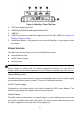
Item Description Protocols ISO 9142-2, ISO 14230-2, ISO 15765-4, K/L-Line, Flashing Code, SAE-J1850 VPW, SAE-J1850 PWM, CAN ISO 11898, Highspeed, Middlespeed, Lowspeed and Singlewire CAN, GM UART, UART Echo Byte Protocol, Honda Diag-H Protocol, TP 2.0, TP 1.6, SAE J1939, SAE J1708, Fault-Tolerant CAN VCI – J2534 ECU Programming Device Functional Description Figure 2-5 J2534 ECU Programming Device 1. DC Power Supply Input Port 2. Vehicle Data Connector 3.
⚫ 6. Lights amber automatically at power up when the device is self-testing USB Port J2534 Programming Capability The J2534 ECU Programming Device is a SAE J2534-1 & -2 compliant PassThru programming interface device. Using the updated OEM software, it is capable of replacing the existing software/firmware in the Electronic Control Units (ECU), programming new ECUs and fixing software-controlled drivability issues and emission issues.
Item Description Wireless Frequency Wireless BT V2.1+EDR, 2.4GHz Input Voltage Range 12 VDC to 24 VDC Supply Current 170 mA @ 12 VDC 100 mA @ 24 VDC Operating Temp. 0°C to 60°C (ambient) Storage Temp. -65°C to 100°C (ambient) Dimensions (L x W x H) 149 mm (5.87”) x 86 mm (3.38”) x 35 mm (1.28”) Weight 290 g (0.64 lb.) NOTE For additional information, please refer to the accompanied user manual for the J2534 ECU Programming Device.
Benz-14 (EU Only) Chrysler-16 (America Only) BMW-20 Kia-20 Mitsubishi/Hyund Nissan-14 GM/Daewoo-12 Honda-3 Benz-38 VW/Audi-2+2 BMW Ethernet Cable ai-12+16 Other Accessories Standard 2.0 USB Cable Connects the tablet to the VCI unit. Mini USB Cable Connects the tablet to the Windows-based PC. AC/DC External Power Adapter Connects the tablet to the external DC power port for power supply. Ethernet Serial Cable Connects the tablet to the VCI unit.
non-OBD II vehicles cannot provide power via the DLC connection. Clipper Cable Provides power to the tablet or the J2534 programming device through connection to the vehicle’s battery. Lighter Fuse x2 A safety device for the cigarette lighter. USB Ethernet Adapter Connects the device to an Ethernet network.
3 Getting Started Make sure the tablet has sufficient power or is connected to the external power supply (see Power Sources on page 5). Power Up Long press the Lock/Power button on the top right side of the tablet to switch the unit on. The power LED will illuminate green. The system boots up and displays the lock screen. Press and drag the inner ring to the edge of the circle to unlock the screen; the MaxiSys Job Menu is shown. Figure 3-1 Sample MaxiSys Job Menu 1. Application Buttons 2.
Application Buttons The table below briefly describes each of the applications in the MaxiSys system. Table 3-1 Applications Name Button Description Diagnostics Accesses the unit’s diagnostics functions. See Diagnostics on page 17. Service Accesses special functions menu. See Service on page 50 for details. MaxiFix Launches the MaxiFix platform that provides the most compatible and abundant repair techniques and diagnostics database. See MaxiFix on page 55.
Name Button Description MaxiScope Configures the unit to operate as an automotive oscilloscope to perform electrical and electronic circuit tests and monitor signal activities. See MaxiScope on page 95. Digital Inspection Configures the unit to operate as a video scope device by connecting to an Imager head cable for close vehicle inspections. See Digital Inspection on page 96.
Name ➢ Button Description VCI Opens the VCI Manager application. The check at the bottom right corner indicates the tablet is communicating with the VCI, an X will display if the tablet is not connected to VCI. MaxiSys Shortcut Returns to the Diagnostics screen. Service Returns to the Service screen. To use the camera: 1. Tap the Camera button. The camera screen opens. 2. Focus the image to be captured in the view finder. 3. Tap the inner blue circle.
Reboot System In case of system crash, long press the Lock/Power button and tap Reboot to restart the system.
4 Diagnostics The Diagnostics application can access the electronic control module of various vehicle control systems, such as engine, transmission, antilock brake system (ABS), airbag system (SRS) and more. Establish Vehicle Communication The Diagnostics operations require connecting the MaxiSys MS908S Pro Diagnostic Platform to the test vehicle through the VCI device using the main cable and test adapters (for non-OBD II vehicles).
2. Connect the cable’s 16-pin male adapter to the vehicle’s DLC, which is generally located under the vehicle dash. NOTE The vehicle’s DLC is not always located under the dash; refer to the user manual of the test vehicle for additional connection information. Non-OBD II Vehicle Connection This type of connection requires both the main cable and a required OBD I adapter for the specific vehicle being serviced.
Figure 4-1 Connection between Cigarette Lighter and Clipper Cable 2. Plug the DC power connector of the cigarette lighter into the DC power supply input port of the J2534 programming device. 3. Connect the clipper cable to the vehicle’s battery. NOTE After the VCI device is successfully connected to the vehicle, the Power LED on the device illuminates, and a brief beep sound will be heard.
are listed in the Setting section on the right side of the screen. NOTE If no VCI device is found, this may indicate that the signal strength of the transmitter is too weak to be detected. In this case try to get closer to the device, or reposition the VCI device, and remove all possible objects that may cause signal interference. When done, tap the Scan button at the top right corner to start searching again. 4.
the loss of signal, check if there are any objects that causes signal interruption. B. ⚫ Check if the VCI device is properly positioned. It is recommended to put the VCI device with the front side up. ⚫ Try standing closer to the VCI device to obtain more stable signals, and faster communication speed. In case of wired connection, check the cable connection between the tablet and the VCI device. ⚫ Check if the green LED on the VCI device is illuminated for BT or USB.
Figure 4-2 Sample Vehicle Menu Screen 1. Top Toolbar Buttons 2. Manufacturer Buttons Top toolbar Buttons The operations of the Toolbar buttons at the top of the screen are listed and described in the table below: Table 4-1 Top Toolbar Buttons Name Button Description Home Returns to the MaxiSys Job Menu. VIN Scan Touching this button opens a dropdown list; tap Auto Detect for auto VIN detection; tap Manual Input to enter VIN manually. All Displays all the vehicle makes in the vehicle menu.
Name Button Description Asia Displays the Asian vehicle menu. Domestic Displays the Domestic vehicle menu. Search Touching this button opens the virtual keyboard, allowing you to manually enter the specific vehicle make required. Cancel Touching this button exits the search screen, or cancels an operation. Manufacturer Buttons The Manufacturer buttons display the various vehicle logos and the brand names.
Vehicle Diagnostics screen directly. Figure 4-3 Sample Vehicle Diagnostics Screen In some cases when users have selected the vehicle brand instead of performing Auto VIN Scan in the first place, the system still provides an option for vehicle VIN scan. Figure 4-4 Sample Vehicle Selection Screen Select Automatic Selection and the system will proceed to acquire VIN information automatically or allow users to input the VIN manually.
➢ To perform Manual VIN Input 1. Tap the Diagnostics application button from the MaxiSys Job Menu. The Vehicle Menu displays. 2. Tap the VIN Scan button on the top toolbar. 3. Select Manual Input. 4. Tap the input box and enter the correct VIN. Figure 4-5 Manual VIN Input 5. Tap Done. The vehicle will be identified in a few seconds, and once the matching is successful, the system will guide you to the Vehicle Diagnostics screen directly (Figure 4-3). 6. Tap Cancel to exit Manual Input.
Navigation This section describes how to navigate the Diagnostics interface and select test options. Diagnostics Screen Layout The Diagnostics screens typically include four sections. Figure 4-6 Sample Diagn ostics Screen 1. Diagnostics Toolbar 2. Status Information Bar 3. Main Section 4. Functional Buttons Diagnostics Toolbar The Diagnostics Toolbar contains a number of buttons that allow you to print or save the displayed data and make other controls.
Name Button Description Print Saves and prints a copy of the displayed data. See Print on page 75. Help Provides instructions or tips for operations of various diagnostic functions. Taps it to open a submenu, on which there are 3 options available to save the displayed data.
➢ To submit Data Logging reports in Diagnostics 1. Tap the Diagnostics application button from the MaxiSys Job Menu. The Data Logging button on the diagnostic toolbar is available throughout the whole Diagnostics operations. 2. Tap the Data Logging button. The button displays blue during the active recording process. 3. Tap the Data Logging button again to finish recording. A submission form will display to let you fill in the report information. 4.
When a user-response is not required to continue, the message displays briefly before automatically disappearing. Warning Messages This type of messages informs you when completing the selected action may result in an irreversible change or loss of data. The typical example for this is the “Erase Codes” message. Error Messages Error messages inform you when a system or procedural error has occurred.
Diagnosis There are two options available when accessing the Diagnosis section: 1. Auto Scan – starts auto scanning for all the available systems on the vehicle 2. Control Units – displays a selection menu of all available control units of the test vehicle. Auto Scan The Auto Scan function performs a comprehensive scanning over all the systems on the vehicle’s ECU in order to locate fault systems and retrieve DTCs.
Column 3 – displays the diagnostic marks indicating different conditions of the test result. -!-: Indicates that the scanned system may not support the code reading function, or there is a communication error between the tester and the control system. -?-: Indicates that the vehicle control system has been detected, but the tester cannot accurately locate it. Fault | #: Indicates there is/are detected fault code(s) present; “#” indicates the number of the detected faults.
Control Units This option allows you to manually locate a required control system for testing through a series of choices. Simply follow the menu driven procedure, and make proper selection each time; the program will guide you to the diagnostic function menu after a few choices you’ve made. Figure 4-8 Sample Function Menu Screen The Function Menu options vary slightly for different vehicles. The function menu may include: ⚫ ECU Information – provides the retrieved ECU information in detail.
NOTE With the diagnostic toolbar on top of the screen throughout the whole diagnostic procedures, you are allowed to make various controls of the diagnostic information at any time, such as printing and saving the displayed data, get help information, or perform data logging. ➢ To perform a diagnostic function 1. Establish communication with the test vehicle via the VCI device. 2. Identify the test vehicle by selecting from the menu options. 3. Select the Diagnosis section. 4.
Read Codes This function retrieves and displays the DTCs from the vehicle’s control system. The Read Codes screen varies for each vehicle being tested, on some vehicles, freeze frame data can also be retrieved for viewing. The sample Read Codes screen displays as below: Figure 4-10 Sample Read Codes Screen 1. Diagnostics Toolbar Buttons – see Table 4-2 Diagnostics Toolbar Buttons on page 26 for details. 2. Main Section 3. ⚫ Column 1 – displays the retrieved codes from the vehicle.
➢ To erase codes 1. Tap Erase Codes from the Function Menu. 2. A warning message displays to inform you of data loss when this function is applied. a) Tap Yes to continue. A confirming screen displays when the operation is successfully done. b) Tap No to exit. 3. Tap ESC on the confirming screen to exit Erase Codes. 4. Check the Read Codes function again to ensure the operation is successful. Live Data When this function is selected, the screen displays the data list for the selected module.
make selection of an item. Tap the check box again to deselect the item. b) ⚫ Value Column – displays the values of the parameter items. ⚫ Range Column – displays the minimum and the maximum limit value. ⚫ Unit Column – displays the unit for the parameter values. ➢ 3. Drop-down Button – tap the drop-down button at the right side of the parameter name to open a submenu, which provides optional modes by which to display the data.
➢ 4. ⚫ Scale Button – tap to change the scale values, which are displayed below the waveform graph. There are four scales available: x1, x2, x4 and x8. ⚫ Zoom-out Button – tap to exit full screen display. To edit the waveform color and line thickness in a data graph 1. Select 1 to 3 parameter items to display in Waveform Graph mode. 2. Tap the Zoom-in Button on the right to display the data graph in full screen. 3. Tap the Edit Button, an edit window appears. 4.
NOTE This mode supports Graph Merge for 2 to 3 parameter items only, select no less than 2 or more than 3 items each time when making graph merge. ➢ To cancel Graph Merge mode, tap the drop-down button on the right side of the parameter name, and select a data display mode. Show Selected/Show All – tap button to exchange between the two options; one displays the selected parameter items, the other displays all the available items.
3. Select a parameter item on the left column, or enter the item name in the Search bar. 4. Tap on the right side of the MIN button, and enter the required minimum value. 5. Tap on the right side of the MAX button, and enter the required maximum value. 6. Tap the ON/OFF button on the right side of the Buzzer Alarm button to turn it on or off. 7. Tap Done to save the setting and return to the Live Data screen; or tap Cancel to exit without saving.
6. Tap Done to save the setting and return to the Live Data screen; or tap Cancel to cancel without saving and exit Setting. ⚫ Done – confirms and saves the setting, and returns you to the Live Data screen. ⚫ Cancel – cancels the setting operation, and returns you to the Live Data screen. Active Test The Active Test function is used to access vehicle-specific subsystem and component tests. Available test vary by manufacturer, year, and model, and only the available tests display in the menu.
complete the tests. Each time when an operation is successfully executed, message such as “Command Finished”, “Activation Successful”, or something similar displays. Tap the ESC functional button to exit the test when finished. Special Functions These functions perform various component adaptations, allowing you to recalibrate or configure certain components after making repairs or replacement.
Tap the ESC button to exit the function. Programming and Coding Since the introduction of OBD II and leading up to modern Hybrids and EVs, computers and software in cars have been expanding at an exponential rate.
Selecting the Programming or Coding function opens a menu of operation options that varies by make and model. Selecting a menu option either shows a programming interface or opens another menu of additional choices. Follow all screen instructions while performing the programming or coding operations. How and what information is presented on the screen varies according to the type of operation being performed.
Figure 4-16 Sample Reprogramming Operation Screen The main section of the reprogramming interface provides you certain hardware version, and current software versions’ information, as well as the information of the newest software versions to be programmed to the control units. Throughout the programming procedure, a series of on-screen operational instructions will display to guide you through. Carefully read the on-screen information and follow the instruction to execute the programming procedure.
Generic OBD II Operations A fast-access option for OBD II/EOBD vehicle diagnosis is available on the Vehicle Menu screen. This option presents a quick way to check for DTCs, isolate the cause of an illuminated malfunction indicator lamp (MIL), check monitor status prior to emissions certification testing, verify repairs, and perform a number of other services that are emissions-related.
NOTE Tap the 4. button beside the protocol name to display additional protocol information. Select a function option to continue. ⚫ DTC & FFD ⚫ I/M Readiness ⚫ Live Data ⚫ O2 Sensor Monitor ⚫ On-Board Monitor ⚫ Component Test ⚫ Vehicle Information ⚫ Vehicle Status NOTE Some functions are supported only on certain vehicles.
⚫ Stored Codes Stored codes are the current emission related DTCs from the ECM of the vehicle. OBD II/EOBD Codes have a priority according to their emission severity, with higher priority codes overwriting lower priority codes. The priority of the code determines the illumination of the Malfunction Indicator Light (MIL) and the codes erase procedure. Manufacturers rank codes differently, so expect to see differences between vehicles.
⚫ This Driving Cycle – displays the status of monitors since the beginning of the current drive cycle. Live Data This function displays the real time PID data from ECU. Displayed data includes analog inputs and outputs, digital inputs and outputs, and system status information broadcast on the vehicle data stream. Live data can be displayed in various modes, see Live Data on page 35 for detailed information.
NOTE Damage to the vehicle electronic control module (ECM) may occur if communication is disrupted. Make sure the all connections, such as data cable, USB cable, and wireless or wired network, are properly connected at all times during testing. Exit all tests before disconnecting the test cable or powering down the tool. ➢ To exit the Diagnostics application 1. From an active diagnostic screen, tap the Back or ESC functional button to exit a diagnostic session step-by-step; Or 2.
5 Service The Service section is specially designed to provide quick access to the vehicle systems for various scheduled service and maintenance tasks. The typical service operation screen is a series of menu driven executive commands. Follow on-screen instructions to select appropriate execution options, enter correct values or data, and perform necessary actions. The application will display detailed instructions to complete selected service operations.
2. All required work must be carried out before the service indicators are reset. Failure to do so may result in incorrect service values and cause DTCs to be stored by the relevant control module. 3. For some vehicles, the scan tool can reset additional service lights such as maintenance cycle and service interval.
Battery Management System (BMS) Service The Battery Management System (BMS) allows the tool to evaluate the battery charge state, monitor the close-circuit current, register the battery replacement, activate the rest state of the vehicle, and charge the battery via the diagnostic socket. NOTE 1. This function is not supported by all vehicles. 2. The sub functions and actual test screens of the BMS may vary by vehicle, please follow the on-screen instructions to make correct option selection.
NOTE 1. Autel accepts no responsibility for any accident or injury arising from servicing the SAS system. When interpreting DTCs retrieved from the vehicle, always follow the manufacturer’s recommendation for repair. 2. All software screens shown in this manual are examples, actual test screens may vary by test vehicle. Pay attention to the menu titles and onscreen instructions to make correct option selections. 3. Before starting procedure, make sure vehicle has an ESC button. Look for button on dash.
3. If the vehicle needs to be driven in order to perform a DPF service, a second person is needed for the function. One person should drive the vehicle while the other person observes the screen on the Tool. Do not attempt to drive and observe the scan tool at the same time. This is dangerous and puts your life and the lives of other motors and pedestrians at risk.
6 MaxiFix The MaxiFix application launches the online troubleshooter database, which not only provides you virtually all common diagnostic trouble code (DTC) database for most vehicles, but also serves as a forum allowing you to network with other MaxiSys users, and gives you access to a vast database of repair and diagnostic tips along with proven fixes.
2. The Main Screen – located at the center of the screen displaying content based on the vehicle attributes and keywords specified. The tabs on the main screen vary in accordance with the section selected on the Navigation Menu, allowing you to switch between functions. 3. The Navigation Menu – the main menu at the bottom of the screen, which provides you access to different sections of MaxiFix.
and filed into an all-in-one information source to provide you with quick and easy repair solutions. On MaxiFix community you can find Tips or share your own Tip to help other community members solve vehicle issues. ➢ To search for a MaxiFix Tip 1. Select a Vehicle. a) Click the “Select Vehicle” button on the Header at the top of the page. b) Select the year of the vehicle from the list. c) Select the make of the vehicle from the list. d) Select the model of the vehicle from the list.
Operations The Navigation Menu is at the bottom of the screen. Selecting the items on the Navigation Menu allows you to switch between the main sections on MaxiFix. These main sections include: ⚫ Home – displays all questions posed and allows you to enter your specific question about one or multiple vehicle makes. ⚫ Search Fix – allows you to search for information from all available resources on MaxiFix, including: Open Questions, Tips, and Real Fixes, and displays search results.
⚫ Tips – presents a list of Tips that directly correlate to your search criteria. Select a Tip from the list to open and review the complete Tip. ⚫ Real Fixes – presents a list of Tips that have been collected from actual shop repair orders and are presented in an easy-to-understand Complaint, Cause, and Correction format. Ask Ask, the third option on the Navigation Menu at the bottom of the screen, allows you to ask a question about a particular vehicle repair issue in the community.
posted to the community ⚫ My Cases – opens a list with links to the closed questions and tips that you have contributed to the community. ⚫ Marked Posts – opens a list with links to Tips and discussions that you are actively participating in. ⚫ My Profile – allows you to view your Autel account information including: your Autel ID, personal information, MaxiFix score, phone number and register time, and edit your portrait. ⚫ Vehicle Preference – used to set up a list of preferred vehicles.
View Profile Information You can view your personal profile by clicking on your account ID or “My Profile” in My MaxiFix section or edit portrait where applicable, and visit other community members’ profile by clicking their portrait. Information included in your profile determines how you are presented to the community, and what type of information will be sent to you from the community.
To close a question, you need to select the question’s response message from the message list on “My Messages” page first, then tap “Adopted Answer” and select “Close Question”. Tap the “Cancel” button to cancel your submission and return to My Messages page. It is strongly recommended to share your repair solutions before closing a question. Your question will be converted to a MaxiFix Community Tip after closing. Score Rewarding System 1.
7 Shop Manager The Shop Manager application helps you manage the workshop information, customer information records, and keep test vehicle history records, which can help in dealing with daily workshop business and improves customer service.
Vehicle History This function stores records of test vehicle history, including vehicle information and the retrieved DTCs from previous diagnostic sessions. Test information is summarized and displayed in an easy-to-view table listing. The Vehicle History also provides direct access to the previously tested vehicle and allows you to restart a diagnostic session without the need to do vehicle identification again. Figure 7-1 Sample Vehicle History Screen 1.
Historical Test Record The Historical Test record of the tested vehicle is a detailed data form, which includes all general information of the vehicle such as vehicle year, make and model and the diagnostic trouble codes retrieved from the previous test sessions, as well as other service details that can be added manually by the technician himself. Figure 7-2 Sample Historical Test Record Sheet ➢ To edit the Historical Test record 1. Tap Shop Manager on the MaxiSys Job Menu. 2. Select Vehicle History.
Workshop Information The Workshop Information form allows you to input, edit, and save the detailed workshop information, such as shop name, address, phone number and other remarks, which, when printing vehicle diagnostic reports and other associated test file, will display as the header of the printed documents. Figure 7-3 Sample Workshop Information Sheet ➢ To edit the Workshop Information sheet 1. Tap the Shop Manager application on the MaxiSys Job Menu. 2. Select Workshop Information. 3.
NOTE The items that must be filled are indicated as required fields. ➢ ➢ 4. Tap the photo frame beside the Name chart to add a photo. A sub menu displays, select Take Photo to take a new photo for the account, or select Choose Photo to choose from the existing files. 5. Some customers may have more than one vehicle for service; you can always add new vehicle information to the account. Tap Add New Vehicle Information, and then fill in the vehicle information. Tap the button to cancel. 6.
3. Select a customer account by tapping the corresponding name card. A Customer Information sheet displays (if Customer Manager is selected). Or, select a vehicle history record to open the Historical vehicle record (if Vehicle History is selected). 4. Tap the History Notes button on the top bar. The History Notes screen displays. Figure 7-4 Sample History Notes Screen 1. Functional Buttons – navigation and function controls. 2.
Name ➢ Button Description Take a Photo Take a photo and add the file to History Notes. Save Save notes. To add a note in History Notes 1. Access History Notes. 2. Tap Add Notes. An edit window displays. 3. Tap on the Title bar to input a note title. 4. Tap on the blank space below to edit a text note or remark. 5. Select a function button on the top to add files in any form you choose. 6. Tap Save to save the note; tap Discard or Cancel to exit without saving.
8 Data Manager The Data Manager application is used to store, print, and review the saved files. Most operations are controlled through the toolbar. Selecting the Data Manager application opens the file system menu. Different file types are sorted separately under different options. Figure 8-1 Sample Data Manager Main Screen Operations Data Manager Operations are based on toolbar controls, details are explained in the following sections.
Figure 8-2 Sample Image Database Screen 1. Toolbar Buttons – used to edit, print and delete the image files. See Table 8-1 Toolbar Buttons in JPG Database on page 71 for detailed information. 2. Main Section – displays the stored images. Table 8-1 Toolbar Buttons in JPG Database Name ➢ Button Description Back Return to the previous screen. Enter Edit Tap to display the editing toolbar to print, delete or view image information. Cancel Tap to close the editing toolbar or cancels file search.
➢ 6. Tap Edit on the top right corner of the window. The editing screen displays. 7. Edit the image information by entering the new file name, and file information. 8. Tap Done to save the information and exit, or tap Cancel to exit without saving. To delete selected images 1. Select Data Manager from the MaxiSys Job Menu. 2. Select Image to access the JPG database. 3. Tap the Enter Edit button to display the editing toolbar. 4.
1. Drop-down Toolbar – tap the button at the top center of the screen to open the Drop-down Toolbar. 2. Main Section – displays the recorded data frames. 3. Navigation Toolbar – allows you to manipulate data playback. Use the Navigation Toolbar buttons to playback the record data from frame to frame. Tap Back to exit data playback. Apps Uninstall This section allows you to manage the firmware applications installed on the MaxiSys Diagnostics System.
9 Settings Selecting Settings application opens a setup interface, on which you can adjust default setting and view information about the MaxiSys system. The following options are available for the MaxiSys system settings: ⚫ Unit ⚫ Language ⚫ Printing Setting ⚫ Wired Network ⚫ Notification Center ⚫ Multitask ⚫ Auto Update ⚫ System Settings ⚫ About Operations This section describes the operation procedures for the settings.
2. Tap the Language option on the left column. 3. Select the required language. A check mark will display to the right of the selected language. 4. Tap the Home button on the top left corner to return to the MaxiSys Job Menu. Or select another setting option for the system setup. Print Printing Setting This option allows you to print any data or information anywhere and anytime either via PC network or WiFi. ➢ To setup the printer connection 1. Tap Settings on the MaxiSys Job Menu. 2.
3. Click Test Print to make sure the printer is working successfully. 4. Tap the Print button on the toolbar of the tablet. A test document will be sent to the computer. ⚫ If the Auto Print option in the MaxiSys Printer is selected, the MaxiSys Printer will print the received document automatically. ⚫ If the Auto Print option is not selected, click Open PDF File button to view all the temporary files. Select the file(s) to print and click Print.
the server for system update notifications or other service information via the Internet. It is highly recommended to keep this function on all the time, so you won’t miss out any new update for MaxiSys or event from Autel. Internet access is required for receiving online messages. ➢ To enable the Notification Center function 1. Tap Settings on the MaxiSys Job Menu. 2. Tap Notification Center on the left column. 3. Tap ON/OFF to enable or disable the Notifications function.
specific time is set, the selected software will be automatically updated at this specific time. System Settings This option provides you a direct access to the Android background system setting interface, on which you can adjust various system settings for the Android system platform, regarding wireless and networks settings, various device settings such as sound and display, as well as system security settings, and check the associated information about the Android system.
10 Update The internal programming of the MaxiSys Diagnostic System, known as the firmware, can be updated using the Update application. Firmware updates increase the MaxiSys applications’ capabilities, typically by adding new tests, new models, or enhanced applications to the database. The display device automatically searches for available updates for all of the Maxisys components when it is connected to the Internet. Any updates that are found can be downloaded and installed on the device.
➢ ⚫ Middle Column – displays a brief introduction about the new changes to the firmware operation or capabilities. Tap button to display an information screen to view more details, and tap the dim area around to close the window. ⚫ Right Column – according to the operation status of each firmware item, the button displays differently. a) Tap Update to update the selected item. b) Tap Pause to suspend the updating procedure. c) Tap Continue to go on updating the suspended update.
11 VCI Manager This application allows you to pair the tablet with the VCI device, MaxiFlash Elite and to check the communication status. Figure 11-1 Sample VCI Manager Screen 1. 2. Connection Mode – there are two connection modes available for selection. The connection state is displayed alongside. ⚫ BT Pairing – when paired to a wireless device, the connection state displays as Paired; otherwise it displays as Unpaired.
BT Pairing The VCI device needs to be either connected to a vehicle or to an available power source, so that it is powered up during the synchronization procedure. Make sure the tablet has a charged battery or is connected to an AC/DC power supply. ➢ To pair the VCI device with the tablet 1. Power on the tablet. 2. Connect the 26-pin end of the data cable to the J2534 ECU Programming Device’s vehicle data connector. 3. Connect the 16-pin end of the data cable to the vehicle data link connector (DLC).
12 Remote Desk The Remote Desk application launches the TeamViewer Quick Support program, which is a simple, fast and secure remote control interface. You can use the application to receive ad-hoc remote support from Autel’s support centre, colleagues, or friends, by allowing them to control your MaxiSys tablet on their PC via the TeamViewer software.
same time, in order to provide support and take control of the tablet remotely. 4. Provide your ID to the partner, and wait for him/her to send you a remote control request. 5. A message displays to ask for your confirmation to allow remote control on your device. 6. Tap Allow to accept, or tap Deny to reject. Refer to the associated TeamViewer documents for additional information.
13 Support This application launches the Support platform which synchronizes Autel’s online service base station with the MaxiSys display tablet. In order to synchronize the device to your online account, you need to register the product through the Internet when you use it for the first time.
⚫ Back – returns to the previous screen, each press takes you one step backwards. ⚫ Forward – each press moves forward one screen until you’ve reached the last screen visited. ⚫ Refresh – reloads and updates the screen. Figure 13-1 Sample Support Application Screen The main section of the Support screen is divided into two sections. The narrow column on the left is the main menu; selecting one subject from the main menu displays the corresponding functional interface on the right.
Service Info The Service Info section displays a detailed record list of the device’s service history information. Every time the device has been sent back to Autel for repair, the device’s serial number and the detailed repair information, such as the fault type, changed components, or system reinstallation will be recorded and updated to the associated online product account that will be synchronized to the Service Info section.
➢ ➢ ⚫ Open – indicates the complaint case has been started but not processed yet ⚫ Suspended – indicates the complaint case is being processed ⚫ Waiting Customer Reply – indicates the complaint has been replied to by the service personnel, and requires feedback from the customer ⚫ Closed – indicates the complaint case has been processed, solved, and ended ➢ To view the detailed complaint session, tap the the case item. button on the right side of To establish a new complaint session 1.
8. Tap the Update button to commit the newest update. Data Logging The Data Logging section keeps records of all sent or unsent (saved) data loggings on the diagnostic system. The support personnel will receive and process the submitted reports through the Support platform. The solution will be sent back within 48 hours. You may continue to correspond with Support until the issue is resolved. Figure 13-3 Sample Data Logging Screen ➢ To make a reply in a Data Logging session 1.
Figure 13-4 Sample Communities Home Screen ➢ ➢ To start a discussion 1. Tap Start a discussion on the Communities Home screen. A list of the major forums is displayed. 2. Based on your interest, select a discussion topic. For example, if you are going to ask a question about the MaxiSys tablet, tap MaxiSys to start a discussion. 3. Input text in the space provided. 4. Select a category or edit tags for the discussed post. This will help members with similar interest to find your post. 5.
User Profile The User Profile section allows you to set a profile photo, check your member status and other information, as well as to review your posts in the communities. Figure 13-5 Sample User Profile Screen Tap the profile photo on the Communities screen to open the User Profile. ⚫ Profile – displays the user’s personal information and member status. The Related links allow you to check the Top Users (ranked according to their points and levels) in the communities, and to connect with other users.
⚫ Shopping & Payment – displays questions and answers about online product purchase and payment methods or procedures.
14 Academy Autel provides various tutorial articles and technical bulletins produced by top-notch technicians and product experts. Please view the materials that are saved on the tablet or view technical articles from our online forum by clicking the links displayed under this application.
15 Quick Link The Quick Link application provides you with convenient access to Autel’s official website and many other well-known sites in automotive service, which offers you abundant information and resources, such as technical help, knowledge base, forums, training, and expertise consultations. Figure 15-1 Sample Quick Link Screen ➢ To open a quick link 1. Tap Quick Link on the MaxiSys Job Menu. The Quick Link application screen displays. 2. Select a website thumbnail from the main section.
16 MaxiScope The MaxiScope application configures the MaxiSys Diagnostic Device to operate as an automotive oscilloscope when used in combination with the MaxiScope module. This function provides all the features needed for performing electrical and electronic circuit tests as well as monitoring signal activities on any modern vehicles, which shows you what is really going on with a vehicle’s electrical system Please download the latest user manual for Autel MaxiScope device from www.autel.com.
17 Digital Inspection The Digital Inspection application configures the MaxiSys Diagnostic Device to operate as a digital video scope by simply connecting the tablet to a Digital Inspection Camera. This function allows you to examine difficult-to-reach areas normally hidden from sight, with the ability to record digital still images and videos, which offers you an economical solution to inspect machinery, facilities, and infrastructure in a safe and quick way.
Additional Accessories The Digital Inspection Camera and its fittings are the additional accessories. Both sizes (8.5 mm and 5.5 mm) of the imager head are optional and available for purchase along with the standard MaxiSys tool kit. Digital Inspection Camera Figure 17-1 Digital Inspection Camera 1. Removable Imager Head Cable – connects to the tool when performing digital inspections for image and video viewing. 2. Handgrip – ergonomically designed handle for comfortable grips and agile operation. 3.
1. Magnet – picks up small metal objects, such as dropped rings or screws. 2. Hook – unclogs obstacles and picks up wires in the pipes or confined areas. 3. Mirror – helps to look around corners and see the unreachable areas. Figure 17-3 5.5mm Imager Head Accessories 1. Mirror – helps to look around corners and see the unreachable areas. 2. Magnet – picks up small metal objects, such as dropped rings or screws. Accessory Assembly For 8.
1. Hold the accessory and the imager head. 2. Screw the thread part of the accessory over the imager head to fix the accessory. Technical Specifications Table 17-1 Specifications Item Optimal Distance Description Viewing 1" to 14" (2.54cm to 35.56cm) with 8.5mm diameter imager head 3/8" to 12" (0.95cm to 30cm) with 5.
Item Description Operating Temperature Main Unit: 0°C to 55°C (ambient) Cable: -10°C to 70°C Storage Temperature -20°C to 75°C (ambient) Waterproof Imager head and cable to 1m Weigh 0.3 kg with 8.5 mm diameter imager head 0.2 kg with 5.5 mm diameter imager head Operations Before performing the Digital Inspection application, the Imager Head Cable must be connected to the tablet through the USB port. Install the correct imager head accessories for use in the appropriate application.
3. Tap the Digital Inspection application on the MaxiSys Job Menu. The Digital Inspection application interface displays, showing a camera operating screen. The default camera is now the Imager head. 4. Select the video icon at the lower right corner to record a video. 5. Properly locate the imager head cable to focus the inspection scene for recording. 6. Tap the red ring on the operating screen to start recording. 7. Tap the red circle again to stop recording.
18 Maintenance and Service To ensure that the tablet and the combined VCI unit perform at their optimum level, we advise that the product maintenance instructions covered in this section is read and followed. Maintenance Instructions The following shows how to maintain your devices, together with precautions to take. ⚫ Use a soft cloth and alcohol or a mild window cleaner to clean the touch screen of the tablet. ⚫ Do not use any abrasive cleansers, detergent, or automotive chemicals to the tablet.
properly updated. B. ⚫ Make sure the tablet is connected to the Internet. ⚫ Check all cables, connections, and indicators to see if the signal is being received. When battery life is shorter than usual: ⚫ This may happen when you are in an area with low signal strength. Turn off your device if is not in use. C. When you cannot turn on the tablet: ⚫ Make sure the tablet is connected to a power source or the battery is charged. D.
⚫ The closer you are to your network’s wireless router, the longer your tablet usage time because less battery power is consumed for the connection. ⚫ The battery recharging time varies depending on the remaining battery capacity. ⚫ Battery life inevitably shortens over time. ⚫ Since overcharging may shorten battery life, remove the tablet from its charger once it is fully charged. Unplug the charger, once charging is complete.
⚫ Phone: (+507) 308-7566 ⚫ Website: www.autel.com/es ⚫ Email: sales.latin@autel.com, latsupport@autel.com ⚫ Address: Office 103, Building 3845, International Business Park, Veracruz, Panamá Pacífico, Panamá AUTEL AUSTRALIA ⚫ Phone: 03 9480 2978 / +61 476293327 ⚫ Website: www.autel.com.au ⚫ Email: sales@autel.com.au ⚫ Address: 155 Islington Street, Melbourne, Collingwood, VIC 3066 For technical assistance in other markets, please contact your local selling agent.
Other Services You can purchase the optional accessories directly from Autel’s authorized tool suppliers, and/or your local distributor or agent.
19 Compliance Information FCC Compliance FCC ID: WQ8MAXISYSMS908S This equipment has been tested and found to comply with the limits for a Class B digital device, pursuant to Part 15 of the FCC Rules. These limits are designed to provide reasonable protection against harmful interference in a residential installation.
power required to reach the network. To avoid the possibility of exceeding the FCC radio frequency exposure limits, human proximity to antenna should be minimized.
20 Warranty 12-Month Limited Warranty Autel Intelligent Technology Corp., Ltd.