Trademarks Autel®, MaxiSys®, MaxiDAS®, MaxiScan®, MaxiRecorder®, MaxiTPMS®, and MaxiCheck® are trademarks of Autel Intelligent Technology Corp., Ltd., registered in China, the United States and other countries. All other marks are trademarks or registered trademarks of their respective holders.
Safety Precautions and Warnings To prevent personal injury or damage to vehicles and/or the scan tool, read this instruction manual first and observe the following safety precautions at a minimum whenever working on a vehicle: Always perform automotive testing in a safe environment. Wear safety eye protection that meets ANSI standards. Keep clothing, hair, hands, tools, test equipment, etc. away from all moving or hot engine parts.
CONTENTS 1 USING THIS MANUAL .................................................................................1 CONVENTIONS .................................................................................................1 2 USING THE SCAN TOOL .............................................................................3 TOOL DESCRIPTION .........................................................................................3 SPECIFICATIONS ..............................................................
1 Using This Manual This manual contains device usage instructions. Some illustrations shown in this manual may contain modules and optional equipment that are not included in your system. Contact your sales representative for availability of other modules and optional tools or accessories. Conventions The following conventions are used. Bold Text Bold text is used to highlight selectable items such as buttons and menu options. Example: Tap OK.
IMPORTANT Keep the cable away from heat, oil, sharp edges and moving parts. Replace damaged cables immediately. Hyperlink Hyperlinks or links that take you to other related articles, procedures, and illustrations are active in electronic documents. Blue italic text indicates a selectable hyperlink and blue underlined text indicates a website link or an email address link. Illustrations Illustrations used in this manual are samples, and the actual testing screen may vary for each vehicle being tested.
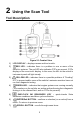
2 Using the Scan Tool Tool Description Figure 2-1 Product View 1) LCD DISPLAY – displays menus and test results. 2) RED LED – indicates there is a problem in one or more of the vehicle’s systems. The red LED also indicates DTCs are present. DTCs display on the scan tool’s display. In this case, the MIL on the vehicle’s instrument panel will light steady. 3) YELLOW LED – indicates there is a possible problem.
8) OBD II CONNECTOR – connects the scan tool to the vehicle’s Data Link Connector (DLC). 9) USB PORT – connects the scan tool to the Mac or Windows PC for upgrading. Specifications Table 2-1 Specifications Item Description Display TFT color display (220x176 dpi) Connectivity USB mini 2.0 OBD II DB16 Operating Temp. 0℃ to 60 ℃ (32℉ to 140℉) Storage Temp. -20℃ to 70 ℃ (-1℉ to 158℉) External Power 8.0 to 18.0V power provided via vehicle battery Dimensions (LxWxH) 120.9 mm (4.76”) x 68.4 mm (2.
Keyboard No solvents such as alcohol are allowed to clean the keypad or display. Use a mild nonabrasive detergent and a soft cotton cloth. Do not soak the keypad as the keypad is not waterproof. Power The scan tool is powered via the vehicle Data Link Connector (DLC). Follow the steps below to turn on the scan tool: 1) Find DLC on vehicle. A plastic DLC cover may be found for some vehicles and you need to remove it before attaching the OBD II cable.
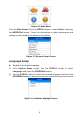
Figure 2-2 Main Menu From the Main Screen: Use the SCROLL button to select Setup, and press the ENTER/Exit button. Follow the instructions to make adjustments and settings as described in the above setup options. Figure 2-3 System Setup Screen Language Setup English is the default language. 1) From System Setup screen, use the SCROLL button to select Language, and press the ENTER/Exit button.
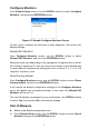
Configure Monitors From System Setup screen, use the SCROLL button to select Configure Monitors, and press the ENTER/Exit button. Figure 2-5 Sample Configure Monitors Screen On this menu, configure the monitors to pass diagnosis, and restore the default settings. Allowed INC Monitors From Configure Monitors screen, use the SCROLL button to select Allowed INC Monitors, and press the ENTER/Exit button. Emissions tests vary depending on the geographic or regional area in which the vehicle is registered.
2) From Unit of Measure screen, use the SCROLL button to select the desired unit of measurement. 3) Press the ENTER/Exit button to save your selection and return to previous menu. Figure 2-6 Sample Unit of Measure Screen Key Beep Set This function allows you to turn on/off the built-in speaker for key pressing. The default setting is Beep On. 1) From System Setup screen, use the SCROLL button to select Key Beep Set and press the ENTER/Exit button.
lights. This function is invaluable when performing diagnostics alone, or while working in bright areas where LED illumination alone is not sufficient. 1) 2) From System Setup screen, use the SCROLL button to select Status Beep Set and press the ENTER/Exit button. From Status Beep Set menu, use the SCROLL button to select Beep ON or Beep OFF to turn on/off the beep. Figure 2-8 Sample Status Beep Set Screen 3) Press the ENTER/Exit button to save your selection and return to previous menu.
Keyboard Test The Keyboard Test function verifies if the keys are functioning properly. 1) Use the SCROLL button to select Keyboard Test from the Tool Selftest menu, and then press the ENTER/Exit button. 2) Press any key to start test. When you press a key, the key name should display on screen. If the key name does not display, the key is not functioning. Figure 2-10 Sample Keyboard Test Screen The OK button refers to ENTER/Exit button. 3) Double press ENTER/Exit to return to previous menu.
Vehicle Info Show Set The default setting is Set On. This function allows you to turn on/off the Vehicle Info display when entering the test vehicle through OBDII function. 1) From System Setup screen, use the UP/DOWN scroll button to select Vehicle Info Show Set and press the OK button. 2) From Vehicle Info Show Set menu, use the UP/DOWN scroll button to select SHOW ON or SHOW OFF to turn on/off the Vehicle Info screen. 3) Press the OK button to save your selection and return to previous menu.
Conditions and click on Agree, and then click Create Autel ID at the bottom. A product registration screen will display. 6. The device’s serial number and password is located in the About section of the Settings application on the tool. 7. Select your product model, enter the product serial number and password on the Product Registration screen, and click Submit to complete the registration procedure. Update Procedure Autel frequently releases software updates to download.
Figure 2-13 Sample Update Window Generally, there are two ways to update programs: Batch Update 1. Select the programs to update by checking the boxes next to those items. Then click the Update All button on the bottom right of screen. Click the Clear All button to deselect files. 2. Or, click on the Select All checkbox on the bottom left of screen and all updatable items will be selected. Click the Update All button on the right of the screen. 3.
2) View tool information on screen. Figure 2-14 Sample About Screen Vehicle Coverage The AutoLink AL329 OBDII/EOBD Scanner is specially designed to work with all OBD II compliant vehicles, including those equipped with Control Area Network (CAN) protocol. The EPA requires all domestic, Asian and European vehicles, 1996 and newer (including light trucks), sold in the United States must be OBD II compliant. A small number of 1994 and 1995 model year gasoline vehicles are OBD II compliant.
Verify that the ignition is ON. Ensure the scan tool’s OBD connected to the vehicle’s DLC. Verify that the vehicle is OBD II compliant. Turn the ignition off and wait for about 10 seconds. Turn the ignition back to on and continue the testing. Verify the control module is not defective. II connector is securely Operating Error If the scan tool freezes, then an exception occurs or the vehicle’s ECU (Engine Control Unit) is too slow to respond to requests.
3 OBD II Diagnostics When more than one vehicle control module is detected by the scan tool, you will be prompted to select the module with retrievable data. The Power train Control Module [PCM] and Transmission Control Module [TCM] are the most commonly scanned modules. CAUTION: Don’t connect or disconnect the scan tool while the ignition is on or the engine running. 1) Turn the ignition off. 2) Locate the vehicle’s 16-pin Data Link Connector (DLC). 3) Plug the tool into the vehicle’s DLC.
Figure 3-1 Sample System Status Screen If more than one module is detected, you will be prompted to select a module to test. Use the SCROLL button to select a module and press the ENTER/Exit button to confirm. Figure 3-2 Sample Control Module Screen Read Codes The Read Codes function can be performed with the key on, engine off (KOEO) or with the key on, engine running (KOER).
monitor for each DTC has determined that the malfunction is no longer present and is not causing the MIL. Permanent DTCs are stored in nonvolatile memory and can not be erased by any diagnostics service or by disconnecting power to ECU. 1) Use SCROLL button to select Read Codes from Diagnostic Menu and press ENTER/Exit button. Figure 3-3 Sample Diagnostic Menu 2) Use the SCROLL button to select Stored Codes or Pending Codes from the Read Codes menu and press the ENTER/Exit button.
4) If more than one DTC is found, use the SCROLL button to review each code. If retrieved DTCs contain any manufacturer specific or enhanced codes, the tool’s AutoVIN technology will automatically display the definition of the code. 5) Select Previous Menu from the Read Codes screen, and press ENTER/Exit button to return to previous menu. Erase Codes NOTE 1.
If the codes are cleared successfully, an “Erase Done!” confirmation message displays. If the codes are not cleared, then an “Erase Failure. Turn Key on with Engine off!” message displays. Figure 3-6 Sample Erase Done Screen Figure 3-7 Sample Erase Failure Screen Live Data The function allows viewing of live or real time PID data of vehicle’s computer module(s). 1) To view live data, use the SCROLL button to select Live Data from Diagnostic Menu and press the ENTER/Exit button.
3) To view complete set of data, use SCROLL button to select Complete Data Set from View Data menu and press the ENTER/Exit button. Figure 3-9 Sample View Data Screen 4) View live PIDs on the screen. Use the SCROLL button for more PIDs if additional information is available on more than one page. Figure 3-10 Sample Live Data Screen The number “x” to the right of the screen indicates the sequence of the highlighted item. 5) Press the ENTER/Exit button to return to previous menu.
2) Wait while the scan tool validates the PID MAP. 3) If retrieved information displays on more than one screen, use the SCROLL button, as necessary, until all the data have shown up. Figure 3-11 Sample View Freeze Frame Screen 4) If no freeze frame data is available, the message “No freeze frame data stored!” displays. Press ENTER/Exit button to return to previous screen.
Retrieve I/M Readiness Status with One-Click I/M Readiness Key Press the One-Click I/M Readiness Key, to retrieve I/M readiness status. The screen will display as below. The LEDs colors and the audio tones indicate readiness status. Figure 3-12 Sample I/M Readiness Screen OK – indicates that a particular monitor being checked has completed its diagnostic testing. INC – indicates that a particular monitor being checked has not completed its diagnostic testing.
The Yellow LED will also light if the monitors do not complete their tests. Each state’s emissions standards differ on the number of tested monitors needed to meet vehicle emissions compliance. NOTE Confer with your automotive technician about the status results of each monitor to determine if the vehicle is ready for your state’s emissions test. 3) RED LED – indicates there is a problem with one or more of the vehicle’s system.
Retrieve I/M Readiness Status in Typical Way 1) Use the SCROLL button to select I/M Readiness from Diagnostic Menu and press ENTER/Exit button. 2) Wait while the scan tool validates the PID MAP. 3) If the vehicle supports both types of tests, then both types will be displayed on the screen for selection. Figure 3-13 Sample I/M Readiness Menu Screen 4) Use the SCROLL button to view the status of the MIL light (ON or OFF) and the following monitors.
BP – Boost Pressure System Monitor EGS – Exhaust Gas Sensor Monitor PM – PM Filter Monitor Figure 3-14 Sample Since DTCs Cleared Screen 5) If the vehicle supports readiness test of This Drive Cycle, a screen of the following displays. Figure 3-15 Sample This Drive Cycle Screen 6) The LEDs and audio tones corresponding to different monitor status will be activated as below.
View Vehicle Information This function enables retrieval of Vehicle Identification No. (VIN), Calibration ID No. (CINs), Calibration Verification No. (CVNs) and In-use Performance Tracking on 2000 and newer vehicles that support Mode 9. 1) 2) Use SCROLL button to select Vehicle Info. from the Diagnostic Menu and press ENTER/Exit button. A message displays to remind you “Turn key on with engine off!” Wait a moment or press any key to continue. Figure 3-16 Sample Vehicle Info.
5) View retrieved vehicle information on screen. 6) Select Previous Menu from the Vehicle Info. screen, and press ENTER/Exit button to return to the previous menu. Figure 3-19 Sample Cal. Verf. Number Screen Exit the OBD II Test 1) To exit OBD II test, use SCROLL button to select Previous Menu from Diagnostic Menu and press ENTER/Exit button. 2) A message displays for your confirmation. Press ENTER/Exit button to exit.
4 Ready Test This function can be used as a convenient readiness test tool by automotive technicians to determine if the tested vehicle is ready for an emission test. By visual and audible indication, you will learn a vehicle’s emissions readiness. General Information Repairs to the emissions-control systems of a 1996 or newer vehicle cause the vehicle’s computer (ECU) memory to be cleared.
Use the SCROLL button to select Ready Test from Main Screen, and press the ENTER/Exit button. Figure 4-1 Main Menu As Post-Repair Diagnostic Tool This function can be used (after the vehicle has done any emission-related repairs) to confirm that the repair has been performed successfully. After repairs, some drive cycles are required to reset the monitoring systems. Drive cycles vary by vehicle and by monitor.
LEDs and audible tone if your vehicle is ready to conduct state emission test. 2) If the GREEN LED lights and two long beeps are heard, your vehicle is ready and it should pass emissions testing. 3) If the RED LED lights, your vehicle is not ready and must be repaired before an emission test can be performed. IMPORTANT If you are driving the vehicle to perform a drive cycle ALONE, set the Status Beep On. The beep signifies that the monitors have run and the diagnostics testing completed.
OK – indicates that a particular monitor being checked has completed its diagnostic testing. INC – indicates that a particular monitor being checked has not completed its diagnostic testing. N/A – the monitor is not supported on the vehicle. The LED and audio tone indications are interpreted as below: LED Interpretation The green and red LEDs provide an easy way to check if emission-related monitoring systems have completed their self-diagnostic testing. 1) GREEN LED – your vehicle is Ready.
5 Compliance Information FCC COMPLIANCE This device complies with Industry Canada’s licence-exempt RSSs. Operation is subject to the following two conditions: 1. This device may not cause harmful interference. 2. This device must accept any interference received, including interference that may cause undesired operation. Cet appareil est conforme aux CNR exempts de licence d’Industrie Canada. Son fonctionnement est soumis aux deux conditions suivantes: 1.
– Connect the equipment into an outlet on a circuit different from that to which the receiver is connected. – Consult the dealer or an experienced radio/TV technician for help. Changes or modifications not expressly approved by the party responsible for compliance could void the user’s authority to operate the equipment. RF WARNING STATEMENT The device has been evaluated to meet general RF exposure requirement. The device can be used in portable exposure condition without restriction.
6 Warranty and Service Limited One Year Warranty Autel Intelligent Technology Corp., Ltd.
Service and Support If you have any questions regarding the product, please contact one of our offices or your local distributor. AUTEL NORTH AMERICA Phone: 855-AUTEL-US (855-288-3587) Monday-Friday 9am-6pm EST Website: www.autel.com Email: ussupport@autel.com Address: 175 Central Avenue, Suite 200, Farmingdale, New York, USA. 11735 AUTEL EUROPE Phone: 0049 (0) 61032000522 Website: www.autel.eu Email: sales.eu@autel.com, support.eu@autel.