Trademarks Autel®, MaxiSys®, MaxiDAS®, MaxiScan®, MaxiRecorder®, MaxiTPMS®, and MaxiCheck® are trademarks of Autel Intelligent Technology Corp., Ltd., registered in China, the United States and other countries. All other marks are trademarks or registered trademarks of their respective holders.
Safety Precautions and Warnings To prevent personal injury or damage to vehicles and/or the scan tool, read this instruction manual first and observe the following safety precautions at a minimum whenever working on a vehicle: Always perform automotive testing in a safe environment. Wear safety eye protection that meets ANSI standards. Keep clothing, hair, hands, tools, test equipment, etc. away from all moving or hot engine parts.
CONTENTS 1 USING THIS MANUAL .................................................................................1 CONVENTIONS .................................................................................................1 2 USING THE SCAN TOOL .............................................................................3 TOOL DESCRIPTION .........................................................................................3 SPECIFICATIONS ..............................................................
READY TEST APPLICATION .............................................................................51 LED AND TONE INTERPRETATION ....................................................................52 6 COMPLIANCE INFORMATION ..................................................................55 7 WARRANTY AND SERVICE ......................................................................57 LIMITED ONE YEAR W ARRANTY.......................................................................
1 Using This Manual This manual contains device usage instructions. Some illustrations shown in this manual may contain modules and optional equipment that are not included in your system. Contact your sales representative for availability of other modules and optional tools or accessories. Conventions The following conventions are used. Bold Text Bold text is used to highlight selectable items such as buttons and menu options. Example: Tap OK.
IMPORTANT Keep the cable away from heat, oil, sharp edges and moving parts. Replace damaged cables immediately. Hyperlink Hyperlinks or links that take you to other related articles, procedures, and illustrations are active in electronic documents. Blue italic text indicates a selectable hyperlink and blue underlined text indicates a website link or an email address link. Illustrations Illustrations used in this manual are samples, and the actual testing screen may vary for each vehicle being tested.
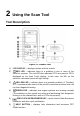
2 Using the Scan Tool Tool Description Figure 2-1 Product View 1) LCD DISPLAY – displays menus and test results. 2) RED LED – indicates there is a problem in one or more of the vehicle’s systems. The red LED also indicates DTCs are present. DTCs displayed on the Scan Tool’s display. In this case, the MIL on the vehicle’s instrument panel will light steady. 3) YELLOW LED – indicates there is a possible problem.
7) ESC BUTTON – cancels a selection (or action) from a menu or returns to the previous screen. 8) LEFT SCROLL BUTTON – when looking up DTC definitions, press to view previous character and to display additional information on previous screens if present; press to deselect all marked PID data when viewing or recording customized live data list; press to view previous frames of recorded data when playing back live data. Press to update DTC library in Update Mode.
Item Description External Power 8.0 to 18.0V power provided via vehicle battery Dimensions (LxWxH) 183 mm (7.2”) x 91 mm (3.58”) x 33 mm (1.3”) Weight 237 g (0.522 lb.) Accessories Included 1) User Manual – instructions on tool operations. 2) Quick Guide – instructions on registering tool and updating software. 3) OBD II Cable – used to connect tool to vehicle for communication and to power tool.
2) Find DLC on vehicle. A plastic DLC cover may be found for some vehicles and you need to remove it before attaching the OBD II cable. 3) Plug OBD II cable to the vehicle’s DLC. DTC Lookup The DTC Lookup function is used to search for definitions of DTCs stored in the DTC library and for DTC Guide information. 1) From Main Screen, use the UP/DOWN scroll button and LEFT/RIGHT scroll button to select DTC Lookup and press the OK button.
UP/DOWN button to view additional information on previous/next screens. If retrieved DTCs contain any manufacturer specific codes, the AutoVIN function embedded in this tool will automatically display the definition of the code. If definition could not be found, the scan tool displays “Please refer to vehicle service manual!” For DTC Guide information, press the “?” Help button. 4) To view previous or next DTC in the built-in DTC library, use the LEFT/RIGHT button.
Figure 2-4 Sample System Setup Screen Language English is the default language. 1) From System Setup screen, use the UP/DOWN scroll button to select Language, and press the OK button. 2) Use the UP/DOWN scroll button to select the desired language and press the OK button to save your selection and return to previous screen. Figure 2-5 Sample Language Screen Configure Monitors From System Setup screen, use the UP/DOWN scroll button to select Configure Monitors, and press the OK button.
Figure 2-6 Sample Configure Monitors Screen On this menu, configure the monitors required to test spark ignition and compression ignition, the number of monitors to pass diagnosis, and restore the default settings. Spark IGN Required Monitors From Configure Monitors screen, use the UP/DOWN scroll button to select Spark IGN Required Monitors, and press the OK button. The monitors for spark ignition engines display as below.
Table 2-3 Compression IGN Required Monitors √ MIS √ BP √ FUEL √ EGS √ CCM √ PM √ HCCAT √ EGR √ NCAT Allowed INC Monitors From Configure Monitors screen, use the UP/DOWN scroll button to select Allowed INC Monitors, and press the OK button. Emissions tests vary depending on the geographic or regional area in which the vehicle is registered.
Figure 2-7 Sample Unit of Measure Screen 3) Press the OK button to save your selection and return to previous menu. Key Beep Set This function allows you to turn on/off the built-in speaker for key pressing. The default setting is Beep On. 1) From System Setup screen, use the UP/DOWN scroll button to select Key Beep Set and press the OK button. 2) From Key Beep Set menu, use the UP/DOWN scroll button to select Beep ON or Beep OFF to turn on/off the beep.
1) From System Setup screen, use the UP/DOWN scroll button to select Status Beep Set and press the OK button. 2) From Status Beep Set menu, use the UP/DOWN scroll button to select Beep ON or Beep OFF to turn on/off the beep. Figure 2-9 Sample Status Beep Set Screen 3) Press the OK button to save your selection and return to previous menu. Tool Self-test The Tool Self-test function checks if the display, LED lamps and keyboard are working properly.
Keyboard Test The Keyboard Test function verifies if the keys are functioning properly. 1) Use the UP/DOWN scroll button to select Keyboard Test from the Tool Self-test menu, and then press the OK button. 2) Press any key to start test. When you press a key, the key name should display on screen. If the key name does not display, the key is not functioning. Figure 2-11 Sample Keyboard Test Screen 3) Double press ESC to return to previous menu.
3) When completed, press the ESC button to exit. Vehicle Info Show Set The default setting is Show On. This function allows you to turn on/off the Vehicle Info display when entering the test vehicle through OBDII function. 1) From System Setup screen, use the UP/DOWN scroll button to select Vehicle Info Show Set and press the OK button. 2) From Vehicle Info Show Set menu, use the UP/DOWN scroll button to select SHOW ON or SHOW OFF to turn on/off the Vehicle Info screen.
NOTE Prior to registration, please confirm your network is working properly. 1. Visit the website http://pro.autel.com. 2. If you already have an Autel account, Sign In with your account ID and password. 3. If you are a new member to Autel, click on the Create Autel ID button on the left side of the screen to create an ID. 4. Enter the required information in the input fields, and click the Get Verification Code button to get a verification code for email validation. 5.
Figure 2-14 Sample Log In Window 3. Connect the scan tool to your computer with the provided USB cable. 4. From System Setup screen in the tool, select Update Mode, and press OK. 5. Enter your Autel ID and password and wait for the Update window to display. If you forget your password, click the [Forget Password?] link to our website and retrieve your password. Or click Sign up to create an Autel ID to continue. 6. Select tool and serial number, click OK to continue. 7.
2. Or, click on the Select All checkbox on the bottom left of screen and all updatable items will be selected. Click the Update All button on the right of the screen. 3. When the download is completed, the programs will be automatically installed. The new version will replace the old version. Single Update 1. Locate the desired update and click the Update button in the same line. 2. The downloaded programs will automatically install. The update will replace the existing version of the software.
A small number of 1994 and 1995 model year gasoline vehicles are OBD II compliant. To verify if a 1994 or 1995 vehicle is OBD II compliant, check the Vehicle Emissions Control Information (VECI) Label which is located under the hood or by the radiator of most vehicles. If the vehicle is OBD II compliant, the label will designate “OBD II Certified”. Additionally, government regulations mandate that all OBD II compliant vehicles must have a “common” sixteen-pin Data Link Connector (DLC).
Turn the ignition off and wait for about 10 seconds. Turn the ignition back to on and continue the testing. Scan tool doesn’t power up If the scan tool won’t power up or operates incorrectly, do the following: Check if the scan tool’s OBD II connector is securely connected to the vehicle’s DLC; Check if the DLC pins are bent or broken. Clean the DLC pins if necessary. Check vehicle battery to make sure it is still good with at least 8.0 volts.
3 Playback The Playback function allows viewing and printing of data from last recorded test. Review Data 1) Use the UP/DOWN scroll button and LEFT/RIGHT scroll button to select Playback from Main Screen, and press the OK button. 2) Select Review Data, and press the OK button. Figure 3-1 Sample Playback Screen 3) Select the desired item from Review Data menu, and press OK.
4) Diagnostics results can be reviewed from this list only when trouble codes are detected in previous tests. Select the Location of the test records. A maximum of three records can be saved. If there is only one record saved in the tool, then only one Location will display. Figure 3-3 Sample Location Selection Screen 5) View the selected data on the screen.
NOTE The print function is not available on Mac for the present. 1. Download the Maxi PC Suite from www.autel.com and install. 2. Connect the tool to the computer using the supplied USB cable. 3. Run Autel Printer software on the computer. 4. Select Playback on the Main Screen of the tool. On the data menu screen, select Print Data and then select the data you want to print. Wait for the review window to display, and then select Print function. The selected file will upload to your computer. 5.
4 OBD II Diagnostics When more than one vehicle control module is detected by the scan tool, you will be prompted to select the module with retrievable data. The Power train Control Module [PCM] and Transmission Control Module [TCM] are the most commonly scanned modules. CAUTION: Don’t connect or disconnect the scan tool while the ignition is on or the engine running. 1) Turn the ignition off. 2) Locate the vehicle’s 16-pin Data Link Connector (DLC). 3) Plug the tool into the vehicle’s DLC.
Review previously stored data before erasing. Figure 4-1 Sample Erase Previous Data Screen 8) To erase the data, press the OK button; if you do not want to erase the data, press ESC to exit or use LEFT/RIGHT button to select NO and press OK to continue. 9) View a summary of system status (MIL status, DTC counts, Monitor status) on screen. Wait a moment or press any key for Diagnostic Menu to display.
Stored Codes are also known as “hard codes”, which are fault codes, or trouble codes that have been stored in the vehicle computer memory because the faults have reoccurred for more than a specified amount of key-cycles. These codes will cause the control module to illuminate the malfunction indicator light (MIL) when emission-related faults occur. Pending Codes are also referred to as “maturing codes” or “continuous monitor codes”.
Figure 4-4 Sample Read Codes Screen The OBD Codes reads pending codes, stored codes, and permanent codes. The Enhanced Codes reads DTCs from engine and transmission systems of GM, Chrysler, and Ford vehicles. If no codes are found, a message will display “No (pending) codes are stored in the module!” Wait a moment or press any key to return to previous screen. NOTE Permanent Codes function is available only for vehicles supporting the CAN protocols. 3) View DTCs and their definitions on screen.
Erase Codes NOTE 1. Erasing the Diagnostic Trouble Codes may allow the scan tool to delete not only the codes from the vehicle’s on-board computer, but also “Freeze Frame” data and manufacturer-specific enhanced data. Further, the I/M Readiness Monitor Status for all vehicle monitors is reset to Not Ready or Not Complete status. Do not erase the codes before repairs or services have been performed. 2. Even if deleted, codes will again display if the underlining fault causing the code is not addressed.
Live Data In this function, you can not only read the live data but also record data for later review. View Data The View Data function allows viewing of live or real time PID data of vehicle’s computer module(s). 1) To view live data, use the UP/DOWN scroll button to select Live Data from Diagnostic Menu and press the OK button. 2) Wait a few seconds while the scan tool validates the PID MAP.
View Complete Data Set 1) To view complete set of data, use UP/DOWN scroll button to select Complete Data Set from View Data menu and press the OK button. 2) View live PIDs on the screen. Use the UP/DOWN scroll button for more PIDs if additional information is available on more than one page. Figure 4-9 Sample View Data Menu Figure 4-10 Sample Complete Data Screen The number “x” to the right of the screen indicates the sequence of the highlighted item.
Figure 4-11 Sample Data Graph Screen 3) Press the ESC button to return to previous menu. View Custom Data Set 1) To view customized PID data, use the UP/DOWN scroll button to select Custom Data Set from View Data menu and press the OK button. 2) Follow on-screen instructions. Figure 4-12 Sample Custom Data Set Screen 1 3) Use the RIGHT button to deselect/select data parameters, and use the UP/DOWN scroll button to move up and down. Selected parameters are marked with solid squares.
4) The number “x” to the upper right corner of the screen indicates the sequence of highlighted item; and “#x” are the order that the parameters are selected and will be displayed. Press the LEFT button to deselect all marketed items or select all items. A message displays for your confirmation. If you decide to deselect these items, press OK; if you decide not to, press ESC or use the LEFT/RIGHT scroll button to select NO to continue PID selections.
To record live data, use the UP/DOWN scroll button to select Record Data from Live Data menu and press the OK button. Record Complete Data Set 1) To record complete set of live data, use the UP/DOWN scroll button to select Complete Data Set from Record Data menu and press the OK button. Figure 4-15 Sample Record Data Screen 2) Use the UP/DOWN scroll button to select a trigger mode and press the OK button.
Figure 4-17 Sample Select Memory Screen 1 The asterisk (*) icon on the screen indicates that a previous recording is stored in the highlighted location. If you select a location marked with an asterisk (*) icon, a message prompting to overwrite old recording displays.
Figure 4-19 Sample Manual Trigger Screen If DTC Trigger is selected, following screen displays: Figure 4-20 Sample DTC Trigger Screen 5) Wait for DTC to trigger or press OK to start recording. Drive till a DTC is detected when DTC Trigger is selected. If no DTCs are detected, press ESC to exit recording. Figure 4-21 Sample Recording Data Screen The number “x/x...” in the upper right corner of the screen indicates the number of recorded frames out of the maximum frames that can be recorded.
6) The scan tool continues to record PID data until the ESC button is pressed, selected memory location is full, or it completes recording. A message will display asking if the recording should be played back. Figure 4-22 Sample Recording Done Screen If you wish to playback recorded data, press the OK button; if you do not wish to playback, press the ESC button, or use LEFT/RIGHT button to select NO and press the OK button to return to Record Data menu.
5) Use the UP/DOWN scroll button to select a memory location and press the OK button. 6) Follow on-screen instructions to select DTC trigger mode. 7) Wait for DTC to trigger recording or press OK to start recording. 8) The scan tool continues recording PID data until user presses ESC button, the selected memory location is full, or it completes recording. A message prompting to playback data shows on the screen.
Figure 4-24 Sample Playback Data Screen 4) Use the LEFT/RIGHT button to view PIDs of next or previous frames. View Freeze Frame Data Freeze Frame Data allows the technician to view the vehicle’s operating parameters at the moment a DTC (Diagnostic Trouble Code) is detected. For example, the parameters may include engine speed (RPM), engine coolant temperature (ECT), or vehicle speed sensor (VSS).
4) To view full name of a PID, use the UP/DOWN scroll button to select the PID, and press the HELP button. 5) Press ESC button to return to previous screen. Retrieve I/M Readiness Status I/M Readiness function is used to check the operations of the Emission System on OBD II compliant vehicles. It is an excellent function to use prior to having a vehicle inspected for state emissions compliance.
Figure 4-26 Sample I/M Readiness Screen The green, yellow and red LEDs provide a quick way to help you determine if a vehicle is ready for an Emission Test. OK – indicates that a particular monitor being checked has completed its diagnostic testing. INC – indicates that a particular monitor being checked has not completed its diagnostic testing. N/A – the monitor is not supported on the vehicle.
The Yellow LED will also light if the monitors do not complete their tests. Each state’s emissions standards differ on the number of tested monitors needed to meet vehicle emissions compliance. NOTE Confer with your automotive technician about the status results of each monitor to determine if the vehicle is ready for your state’s emissions test. RED LED – indicates there is a problem with one or more of the vehicle’s system.
Retrieve I/M Readiness status in typical way 1) Use the UP/DOWN scroll button to select I/M Readiness from Diagnostic Menu and press OK button. 2) Wait while the scan tool validates the PID MAP. 3) If the vehicle supports both types of tests, then both types will be displayed on the screen for selection. Figure 4-27 Sample I/M Readiness Selection Screen 4) Use the UP/DOWN scroll button to view the status of the MIL light (ON or OFF) and the following monitors.
EGR – EGR System Monitor HCCAT – NMHC Catalyst Monitor NCAT – NOx Aftertreatment Monitor BP – Boost Pressure System Monitor EGS – Exhaust Gas Sensor Monitor PM – PM Filter Monitor Figure 4-28 Sample Since DTC Cleared Screen 5) If the vehicle supports readiness test of This Drive Cycle, a screen of the following displays. Figure 4-29 Sample This Drive Cycle Screen 6) The LEDs and audio tone corresponding to different monitor status will be activated as below.
7) Use the UP/DOWN scroll button for more PIDs if additional information is available on more than one page. Or use the LEFT/RIGHT scroll button to view PIDs in the previous/next page. 8) Press the ESC button to return to Diagnostic Menu. O2 Monitor Test OBD II regulations set by the (Society of Automotive Engineers) SAE require vehicles monitors and tests on the oxygen (O2) sensors to identify problems related to fuel efficiency and vehicle emissions.
4) View test results of selected O2 sensor. Figure 4-31 Sample O2 Monitor Test Screen 2 5) Use the UP/DOWN scroll button to view additional data if available. 6) Press the ESC button to return to the previous menu. On-Board Monitor Test The On-Board Monitor Test is useful after servicing or after erasing a vehicle’s control module memory.
minimum and maximum value, the scan tool determines if the components and monitors are OK. 1) Use the UP/DOWN scroll button to select On-Board Mon. Test from Diagnostic Menu and press the OK button. 2) Wait while the scan tool validates the PID MAP. 3) The scan tool will prompt you to select the vehicle make. 4) After you select the vehicle manufacturer, the scan tool displays the OnBoard Monitors test results for specific monitored systems. 5) From On-Board Mon.
7) View test data on screen. Figure 4-34 Sample On-board Mon. Test Screen 3 NOTE If the On-Board Monitor Test fails, this monitor item will be listed in red. Figure 4-35 Sample On-board Mon. Test Screen 4 8) Press ESC button to return to the previous menu. Component Test The Component Test initiates a leak test for the vehicle's EVAP system. The scan tool itself does not perform the leak test, but commands the vehicle's on-board computer to start the test.
Figure 4-36 Sample Component Test Screen 1 3) If the test has been initiated by the vehicle, a confirmation message will be displayed on the screen. Figure 4-37 Sample Component Test Screen 2 Some vehicles do not allow scan tools to control vehicle systems or components. If the vehicle under test does not support the EVAP Leak Test, the message, “The select mode is not supported” will display.
View Vehicle Information The Vehicle Info. function enables retrieval of Vehicle Identification No. (VIN), Calibration ID Nos. (CINs), Calibration Verification Nos. (CVNs) and In-use Performance Tracking on 2000 and newer vehicles that support Mode 9. 1) Use UP/DOWN scroll button to select Vehicle Info. from the Diagnostic Menu and press OK button. 2) A message displays to remind you to “Turn key on with engine off!” Wait a moment or press any key to continue. Figure 4-39 Sample Vehicle Info.
Figure 4-41 Sample Vehicle Info. Screen 3 6) Press the ESC button to return to previous menu. Modules Present The Modules Present function displays the module IDs and communication protocols for OBD II modules in the vehicle. 1) Use the UP/DOWN scroll button to select Modules Present from Diagnostic Menu and press OK button. 2) View modules present with their IDs and communication protocols. Figure 4-42 Sample Modules Present Screen 3) Press the ESC button to return to previous menu.
5 Ready Test This function can be used as a convenient readiness test tool by automotive technicians to determine if the tested vehicle is ready for an emission test. By visual and audible indication, you will learn a vehicle’s emissions readiness. General Information Repairs to the emissions-control systems of a 1996 or newer vehicle cause the vehicle’s computer (ECU) memory to be cleared.
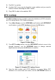
Ready Test Application This function displays which vehicle monitors have run, if they have been completed and the results of the testing. Results display on one screen providing an at-a-glance profile of the vehicle. Use the UP/DOWN scroll button and LEFT/RIGHT scroll button to select Ready Test from Main Screen, and press the OK button.
5) If the RED LED lights, your vehicle is not ready and if you have performed repairs, they have failed to correct the emissions issue. As pre-check diagnostic tool Prior to having a vehicle inspected for state emissions compliance, use this function to check the readiness status. 1) While the scan tool is connected to the vehicle, select Ready Test from Main Screen.
Figure 5-2 Sample I/M Readiness Screen If the scan tool is idle, the result will immediately display. If it is busy, it will wait till the current procedure finished. After viewing the status, press ESC button to exit. OK – indicates that a particular monitor being checked has completed its diagnostic testing. INC – indicates that a particular monitor being checked has not completed its diagnostic testing. N/A – the monitor is not supported on the vehicle.
Table 5-1 LED Light Audio Tone Beep Interval Green Two long beeps 2 minutes Red No beep 54
6 Compliance Information FCC COMPLIANCE This device complies with Industry Canada’s licence-exempt RSSs. Operation is subject to the following two conditions: 1. This device may not cause harmful interference. 2. This device must accept any interference received, including interference that may cause undesired operation. Cet appareil est conforme aux CNR exempts de licence d’Industrie Canada. Son fonctionnement est soumis aux deux conditions suivantes: 1.
– Increase the separation between the equipment and receiver. – Connect the equipment into an outlet on a circuit different from that to which the receiver is connected. – Consult the dealer or an experienced radio/TV technician for help. Changes or modifications not expressly approved by the party responsible for compliance could void the user’s authority to operate the equipment. RF WARNING STATEMENT The device has been evaluated to meet general RF exposure requirement.
7 Warranty and Service Limited One Year Warranty Autel Intelligent Technology Corp., Ltd.
IMPORTANT All contents of the product may be deleted during the process of repair. You should create a back-up copy of any contents of your product before delivering the product for warranty service. Service and Support If you have any questions regarding the product, please contact one of our offices in your region. AUTEL NORTH AMERICA Phone: 855-AUTEL-US (855-288-3587) Monday-Friday 9am-6pm EST Website: www.autel.com Email: ussupport@autel.
Address: Office 103, Building 3845, International Business Park, Veracruz, Panamá Pacífico, Panamá AUTEL AUSTRALIA Phone: 03 9480 2978 / +61 476293327 Website: www.autel.com.au Email: sales@autel.com.au Address: 155 Islington Street, Melbourne, Collingwood, VIC For technical assistance in other markets, please contact your local distributor.