Table of Contents 1. SAFETY PRECAUTIONS AND WARNINGS .............................................. 1 2. GENERAL INFORMATION .......................................................................... 2 2.1 ON-BOARD DIAGNOSTICS (OBD) II ............................................................. 2 2.2 DIAGNOSTIC TROUBLE CODES (DTCS) ........................................................ 2 2.3 LOCATION OF THE DATA LINK CONNECTOR (DLC) .................................... 3 2.
5.7 ON-BOARD MONITOR TEST ........................................................................ 57 5.8 COMPONENT TEST ...................................................................................... 60 5.9 VIEWING VEHICLE INFORMATION .............................................................. 62 5.10 MODULES PRESENT .................................................................................... 63 6. READY TEST .........................................................................
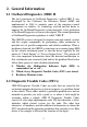
1. Safety Precautions and Warnings To prevent personal injury or damage to vehicles and/or the scan tool, read this instruction manual first and observe the following safety precautions at a minimum whenever working on a vehicle: Always perform automotive testing in a safe environment. Wear safety eye protection that meets ANSI standards. Keep clothing, hair, hands, tools, test equipment, etc. away from all moving or hot engine parts.
2. General Information 2.1 On-Board Diagnostics (OBD) II The first generation of On-Board Diagnostics (called OBD I) was developed by the California Air Resources Board (ARB) and implemented in 1988 to monitor some of the emission control components on vehicles. As technology evolved and the desire to improve the On-Board Diagnostic system increased, a new generation of On-Board Diagnostic system was developed. This second generation of On-Board Diagnostic regulations is called "OBD II".
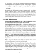
2.3 Location of the Data Link Connector (DLC) The DLC (Data Link Connector or Diagnostic Link Connector) is the standardized 16-cavity connector where diagnostic scan tools interface with the vehicle's on-board computer. The DLC is usually located 12 inches from the center of the instrument panel (dash), under or around the driver‟s side for most vehicles. If Data Link Connector is not located under dashboard, a label should be there telling location.
2.4 OBD II Readiness Monitors An important part of a vehicle‟s OBD II system is the Readiness Monitors, which are indicators used to find out if all of the emissions components have been evaluated by the OBD II system. They are running periodic tests on specific systems and components to ensure that they are performing within allowable limits. Currently, there are eleven OBD II Readiness Monitors (or I/M Monitors) defined by the U.S. Environmental Protection Agency (EPA).
The following monitors are to be used for spark ignition engines only: 1) 2) 3) 4) 5) 6) 7) EGR System O2 Sensors Catalyst Evaporative System O2 Sensor Heater Secondary air Heated Catalyst The following monitors are to be used for compression ignition engines only: 1) 2) 3) 4) 5) 6) EGR System NMHC Catalyst NOx aftertreatment Boost pressure system Exhaust gas sensor PM filter 2.
to “Not Ready”. Since the three continuous monitors are constantly evaluating, they will be reported as “Ready” all of the time. If testing of a particular supported non-continuous monitor has not been completed, the monitor status will be reported as “Not Complete” or “Not Ready.” In order for the OBD monitor system to become ready, the vehicle should be driven under a variety of normal operating conditions.
OBD II Drive Cycle -- A specific mode of vehicle operation that provides conditions required to set all the readiness monitors applicable to the vehicle to the “ready” condition. The purpose of completing an OBD II drive cycle is to force the vehicle to run its onboard diagnostics. Some form of a drive cycle needs to be performed after DTCs have been erased from the PCM‟s memory or after the battery has been disconnected.
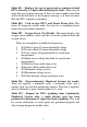
Mode $03 – Displays the type of powertrain or emission related DTCs stored by a 5 digit code identifying the faults. There may be more than one response message if there are more trouble codes than will fit in the data bytes of the response message, or if there are more than one ECU computer responding. Mode $04 – Used to clear DTCs and Freeze Frame data. This clears all diagnostic trouble codes that may be set including freeze frame data and readiness monitors. Mode $05 – Oxygen Sensor Test Results.
Mode $08 – This special Control Mode requests control of the on-board system, test, or component bi-directionally (where applicable). This mode is manufacturer specific. Mode $09 – Reports vehicle information. This information includes vehicle VIN number and calibration information stored in the vehicle ECUs. Mode $0A – Request Emission-Related Diagnostic Trouble Codes with Permanent Status. This mode is required for all emissions-related DTCs.
3. Using the Scan Tool 3.1 Tool Description 1) 2) 3) OBD II CONNECTOR – Connects the scan tool to the vehicle‟s Data Link Connector (DLC). LCD DISPLAY – Indicates test results. GREEN LED – Indicates that engine systems are running normally (The number of monitors on the vehicle which are active and performing their diagnostic testing is in the allowed limit, and no DTCs are present).
4) YELLOW LED – Indicates there is a possible problem. A “Pending” DTC is present and/or some of the vehicle‟s emission monitors have not run their diagnostic testing. 5) RED LED – Indicates there is a problem in one or more of the vehicle‟s systems. The red LED is also used to show that DTCs are present. DTCs are shown on the Scan Tool‟s display. In this case, the MIL lamp on the vehicle‟s instrument panel will light steady on.
recording customized live data list, and views next frames of data when playing back live data. DOWN SCROLL BUTTON – Moves down through menu and submenu items in menu mode. When more than one screen of data is retrieved, moves down through the current screen to next screens for additional data. 14) VΩ TERMINAL – Assists voltage and/or resistance test as a lead. 13) 15) COM TERMINAL – Assists test as a ground lead. 16) mA TERMINAL – Assists current (0~200mA) test as a lead.
2) 3) 4) 5) 6) CD -- Includes user‟s manual, MaxiLink update software, and etc. OBD2 cable -- Provides power to tool and communicates between tool and vehicle. USB cable -- Used to upgrade the scan tool, and to print retrieved data. 3.7V Li-ion battery -- Provides power when disconnected with vehicle. Probes -- Contacts the circuit or component to be tested. AutoLink AL539 Only: 7) Protective Nylon Case – Contains the main unit and cables while not in use.
Before using the scan tool, you must provide power to it. There are five methods for providing power to the scan tool. Cable connection to vehicle. AC/DC external power adapter. Li-ion battery. USB port. Battery test cable. During vehicle testing, power for the scan tool is usually provided through the vehicle cable connection. The detailed instructions show as below: 1) Connect the OBD II Cable to scan tool. 2) Find DLC on vehicle.
Using your computer If you want to charge the tool using your computer, make sure that your computer is turned on, it isn't sleeping (refer to the computer's manual to find out how to turn sleep off), and that the USB you connect the tool to provides power. Also, make sure to use the high-powered USB ports which are typically found on the computer itself ----- not on your keyboard, which is low-powered.
3.7 DTC Lookup The DTC Lookup function is used to search for definitions of DTCs stored in the DTC library and for code breaker information. 1) From Main Screen (Figure 3.1), use the UP/DOWN scroll button and LEFT/RIGHT scroll button to select DTC Lookup and press the OK button. Figure 3.1 2) From DTC Lookup screen, use the LEFT/RIGHT button to move to the desired character, use the UP/DOWN button to change selected digit/character and press the OK button to confirm. (Figure 3.
For manufacturer specific codes, you need to select a vehicle make on an additional screen to look for DTC definitions. If definition could not be found (SAE or Manufacturer Specific), the scan tool displays “Please refer to vehicle service manual!” For code breaker information, you need to press the “?” Help button.
To enter the Setup menu From the Main Screen: Use the UP/DOWN scroll button and LEFT/RIGHT scroll button to select Setup, and press the OK button. Follow the instructions to make adjustments and settings as described in the above setup options. (Figure 3.3) System Setup Language Configure Monitors Unit of Measure Key Beep Set Status Beep Set Tool Self-test Tool Information 1/8 ? Figure 3.3 Language Setup English is the default language.
Configure Monitors From System Setup screen, use the UP/DOWN scroll button to select Configure Monitors, and press the OK button. (Figure 3.5) Configure Monitors 1/4 Spark IGN Required Monitors Compression IGN Required Monitors Allowed INC Monitors ? Reset Factory Default Figure 3.5 In this menu, you could configure the monitors required to test spark ignition and compression ignition, the number of monitors to pass diagnosis, and restore the default settings.
From Configure Monitors screen, use the UP/DOWN scroll button to select Compression IGN Required Monitors, and press the OK button. The monitors for compression ignition engines list as below: Compression IGN Required Monitors √ √ √ √ √ 3) √ √ √ √ MIS FUEL CCM HCCAT NCAT BP EGS PM EGR Allowed INC Monitors From Configure Monitors screen, use the UP/DOWN scroll button to select Allowed INC Monitors, and press the OK button.
Unit of Measure Metric is the default measurement unit. 1) From System Setup screen, use the UP/DOWN scroll button to select Unit of Measure and press the OK button. 2) From Unit of Measure screen, use the UP/DOWN scroll button to select the desired unit of measurement. (Figure 3.6 ) Unit of Measure 1/2 English Metric ? Figure 3.6 3) Press the OK button to save your selection and return to previous menu.
Key Beep Set 1/2 Beep ON Beep OFF ? Figure 3.7 3) Press the OK button to save your selection and return to previous menu. Status Beep Set The default setting is Beep On. This function allows you to turn on/off the build-in speaker for the LEDs in diagnostic testing. Different audio tone corresponds to different LED lamp. This function is invaluable when performing diagnostics alone, or working in bright areas where LED illumination alone is not sufficient.
3) Press the OK button to save your selection and return to previous menu. Tool Self-test The Tool Self-test function checks if the display, LED lamps and keyboard are working properly. A. Display test The Display Test function checks if the LCD display is working normally. 1) From System Setup screen, use the UP/DOWN scroll button to select Tool Self-test, and press the OK button. 2) Select Display Test from Tool Self-test menu and press the OK button to start test. (Figure 3.
2) Press any key to start test. When you press a key, the key name should be observed on the display. If the key name does not show up, then the key is not functioning properly. (Figure 3.10) Keyboard Test Press any key to start test key: Double [ESC] to return Figure 3.10 3) C. Double press ESC to return to previous menu. LED Test The LED Test function verifies if the I/M Readiness LED indicator lamps are functioning properly.
Tool Information The Tool Information function allows viewing of some important information such as serial number and software version number of the scanner. 1) From System Setup screen, use the UP/DOWN scroll button to select Tool Information, and press the OK button; wait for the Tool Information screen to appear. 2) View tool information on screen. (Figure 3.12) . Figure 3.12 Update Mode This function allows you to update the scan tool software and DTC library through a computer.
3) Connect the scan tool to your computer through the USB cable provided. 4) From System Setup screen in scan tool, use the UP/DOWN scroll button to select Update Mode, and press the OK button. 5) Select the programs to be updated in your computer. There are two types of programs: operating system and DTC library. (Figure 3.13) 6) Click Update in the MaxiLink Tool Kit window to begin updating. Figure 3.13 7) During the update procedure, the scan tool displays a message “Update Program.
3.9 Vehicle Coverage The AutoLink AL539/AL539b OBDII/EOBD Scanner is specially designed to work with all OBD II compliant vehicles, including those equipped with universal protocol -- Control Area Network (CAN). It is required by EPA that all 1996 and newer vehicles (cars and light trucks) sold in the United States must be OBD II compliant and this includes all Domestic, Asian and European vehicles. A small number of 1994 and 1995 model year gasoline vehicles are OBD II compliant.
Verify the control module is not defective. Operating Error If the scan tool freezes, then an exception occurs or the vehicle‟s ECU (Engine Control Unit) is too slow to respond to requests. You need to do the following to reset the tool: Reset the scan tool. Turn the ignition off and wait for about 10 seconds. Turn the ignition back to on and continue the testing.
4. Review Data The Review Data function allows viewing of data from last test recorded by the scan tool. 1) Use the UP/DOWN scroll button and LEFT/RIGHT scroll button to select Review Data from Main Screen, and press the OK button. (Figure 3.1) 2) Use the UP/DOWN scroll button to select the desired item from Review Data menu, and press the OK button. (Figure 4.1 ) Review Data 1/6 Live Data Pending Codes View Freeze Frame I/M Readiness On-Board Mon. Test Modules Present ? Figure 4.
5. OBDII Diagnostics When more than one vehicle control module is detected by the scan tool, you will be prompted to select the module where the data may be retrieved. The most often to be selected are the Power train Control Module [PCM] and Transmission Control Module [TCM]. CAUTION: Don’t connect or disconnect any test equipment with ignition on or engine running. 1) 2) 3) 4) 5) Turn the ignition off. Locate the vehicle‟s 16-pin Data Link Connector (DLC).
Review previously stored data thoroughly before erasing. Diagnostic Erase previously stored data to save data from this test? YES NO Figure 5.1 If no data is stored in the scan tool, above prompt will not show up. 8) If you wish to erase the data, press the OK button; if you do not want to erase the data, press ESC to exit or use LEFT/RIGHT button to select NO and press OK to continue. 9) View a summary of system status (MIL status, DTC counts, Monitor status) on screen. (Figure 5.
Control Module 1/2 Engine Module $A4 Figure 5.3 Use the UP/DOWN scroll button to select a module and press the OK button. 5.1 Reading Codes Reading Codes can be done with the key on engine off (KOEO) or with the key on engine running (KOER). Stored Codes are also known as “hard codes”, which are fault codes, or trouble codes that have been stored in the vehicle computer memory because the faults have reoccurred for more than a specified amount of key-cycles.
1) Use UP/DOWN scroll button to select Read Codes from Diagnostic Menu and press OK button. Diagnostic Menu 1/11 Read Codes Erase Codes Live Data View Freeze Frame I/M Readiness O2 Monitor Test ? Figure 5.4 2) Use the UP/DOWN scroll button to select Stored Codes or Pending Codes from the Read Codes menu and press the OK button. Read Codes 1/3 Stored Codes Pending Codes Permanent Codes ? Figure 5.
1/1 P1633 $10 BUICK Ignition 0 Switch Circuit Figure 5.6 4) If more than one DTC is found, use the LEFT/RIGHT scroll button to check all the codes. If retrieved DTCs contain any manufacturer specific or enhanced codes, a “Manufacturer specific codes are found! Press any key to select vehicle make!” message comes up prompting you to select vehicle manufacturer to view DTC definitions. Use UP/DOWN scroll button to select manufacturer and then press OK button to confirm.
enhanced data. Further, the I/M Readiness Monitor Status for all vehicle monitors is reset to Not Ready or Not Complete status. Do not erase the codes before the system has been checked completely by a technician. NOTE: Erasing codes does not mean that trouble codes in ECU have been eliminated completely. As long as there is fault with the vehicle, the trouble codes keeps on presenting. This function is performed with key on engine off (KOEO). Do not start the engine.
Erase Codes Erase Done! Press any key to con. Figure 5.9 If the codes are not cleared, then an “Erase Failure. Turn Key on with Engine off!‖ message appears. Erase Codes Erase Failure. Turn Key on with Engine Off! Press any key to con. Figure 5.10 4) Press any button to return to Diagnostic Menu. 5.3 Live Data In this function, you can not only read the live data but also record data for later review.
2) Wait a few seconds while the scan tool validates the PID MAP. (Figure 5.11) Live Data Reading PID.01 - Please Wait - Figure 5.11 3) Use the UP/DOWN scroll button to select View Data from Live Data menu and press the OK button. ……………… .Live Data View Data Record Data Playback Data 1/3. ? Figure 5.12 Viewing Complete Data Set 1) To view complete set of data, use UP/DOWN scroll button to select Complete Data Set from View Data menu and press the OK button.
…………………View Data 1/3. Complete Data Set Custom Data Set Unit of Measure ? Figure 5.13 2) View live PIDs on the screen. Use the UP/DOWN scroll button for more PIDs if additional information is available on more than one page. Live Data DTC_CNT FUELSYS1 FUELSYS2 LOAD_PCT (%) ETC(℃) SHRTFT1 (%) 6 0 0L -- ? 0.0 -40 99.2 Figure 5.14 The number “x” to the right of the screen indicates sequence of the highlighted item. If the “G” icon appears when a PID is highlighted, graphic information is available.
3) Press the ESC button to return to previous menu. Viewing Custom Data Set 1) To view customized PID data, use the UP/DOWN scroll button to select Custom Data Set from View Data menu and press the OK button. (Figure 5.13) 2) Observe on-screen instructions. ……………Custom Data Set……… ….. [ ] – Select/Deselect [ ] – Deselect all [OK] – Confirm [ESC] – Cancel Press any key to continue. Figure 5.
If you want to deselect all marked items or select all items, press the LEFT button. A message comes up to ask for your confirmation. ………………Deselect All…………………. Deselect all selected PID’s? YES NO Figure 5.18 4) If you decide to deselect these items, press OK; if you decide not to, press ESC or use the LEFT/RIGHT scroll button to select NO to continue PID selections. Press the OK button to view selected PIDs on screen. ………………….Live Data DTC_CNT FUELSYS2 ETC(℃) SHRTFT1 (%) 4. 0 0L -40 99.
There are two trigger modes used to record data: A. Manual Trigger - allows user to press the OK button to start recording. B. DTC Trigger - automatically records PID data when a fault that causes a DTC to set is detected by vehicle. CAUTION: DO NOT try to drive and operate the scan tool at the same time! Always have another person operate the scan tool while driving. To record live data, use the UP/DOWN scroll button to select Record Data from Live Data menu and press the OK button. (Figure 5.
…….……Pick Trigger Mode 1/2 Manual Trigger DTC Trigger ? Figure 5.21 3) If data from previously tested vehicle is not erased, data from current test will be stored in a temporary cache. Use the UP/DOWN scroll button to select a memory location and press the OK button. …………….Select Memory Location #1 Location #2 Location #3 1/3.. * ? Figure 5.22 The asterisk (*) icon on the screen indicates that there is a previous recording in the memory location.
4) If you wish to proceed with overwriting the old recording, press the OK button; if you do not wish to overwrite it, use the LEFT/RIGHT button to select NO or press the ESC button to pick another memory location. Observe on-screen instructions. If Manual Trigger is selected, following screen shows: ……………Manual Trigger……………... Ready to record! Press [ENTER] to start recording… Press [ESC] to exit Figure 5.24 If DTC Trigger is selected, following screen shows: ………………….DTC Trigger……………..
…….Recording…. 5/46 ….. DTC_CNT FUELSYS1 FUELSYS2 LOAD_PCT(%) ETC(℃) SHRTFT1(%) 0 0L -- ? 0.0 -40 99.2 Figure 5.26 6) The number “x/x...” to the upper right corner of the screen indicates the maximum frames that can be recorded and the number of recorded frames. The scan tool keeps recording PID data until user presses the ESC button, selected memory location is full, or it completes recording. A message prompting to playback data shows on the screen.
2) Observe on-screen instructions. (Figure 5.16). Press the OK button to continue; press the ESC button, or use LEFT/RIGHT button to select NO and press the OK button to return to Record Data menu. 3) Use the RIGHT button select/deselect data parameters. Selected parameters are marked with solid squares. Press the OK button to confirm. (Figure 5.17) 4) If you wish to deselect all marked items, press LEFT button. A message comes up to ask for your confirmation.( Figure 5.
If Manual Trigger is selected, following screen shows: (Figure 5.24) If DTC Trigger is selected, following screen shows: (Figure 5.25) 7) Wait for DTC to trigger recording or press OK to start recording. (Figure 5.26) 8) The scan tool keep recording PID data until user presses ESC button, the selected memory location is full, or it completes recording. A message prompting to playback data shows on the screen. (Figure 5.
Select Memory Location #1 Location #2 Location #3 3/3 * * ? Figure 5.28 3) If there is no recording in selected location, a message “Not Supported or Stored No Data” displays on the screen. Use the UP/DOWN button to view recorded PIDs of each frame. 1 of 135 frame DTC_CNT FUELSYS1 FUELSYS2 LOAD_PCT (%) ETC(℃) SHRTFT1(%) … 6 0 OL N/A ? 0.0 -40 99.2 Figure 5.29 4) Use the LEFT/RIGHT button to view PIDs of next or previous frames.
Freeze Frame Data allows the technician to view the vehicle‟s operating parameters at the moment a DTC (Diagnostic Trouble Code) is detected. For example, the parameters may include engine speed (RPM), engine coolant temperature (ECT), or vehicle speed sensor (VSS) etc. This information will aid the technician by allowing the parameters to be duplicated for diagnostic and repair purposes.
……………… ..FUELSYS1……… ……. Fuel System 1 Status Figure 5.32 5) Press ESC button to return to previous screen. 5.5 Retrieving I/M Readiness Status I/M Readiness function is used to check the operations of the Emission System on OBD2 compliant vehicles. It is an excellent function to use prior to having a vehicle inspected for compliance to a state emissions program. CAUTION - by clearing trouble codes you also clear the readiness status for the individual emission system readiness tests.
―INC‖ -- Indicates that a particular monitor being checked has not completed its diagnostic testing. ―N/A‖ -- The monitor is not supported on that vehicle. There are two ways to retrieve I/M readiness status. A. Retrieve I/M Readiness status with One-Click I/M Readiness Key By simply pressing the One-Click I/M Readiness Key, you can retrieve the I/M readiness status. The screen will show as below. (Figure 5.
LED Interpretation 1) GREEN LED – Indicates that engine systems are “OK” and operating normally (the number of Monitors supported by the vehicle which have run and performed their self-diagnostic testing is in the allowed limit. MIL is off. ).There are no stored and pending DTCs. The vehicle is ready for an Emissions Test, and there is a good possibility that it can be certified. 2) YELLOW LED – With MIL off, there may be three possible conditions to cause the yellow LED to light.
Emissions Test can be performed. It is also suggested that the vehicle be inspected/repaired before driving the vehicle further. If the RED LED was obtained, there is a definite problem present in the system(s). In these cases, you have the following options: Repair the vehicle yourself. If you are going to perform the repairs yourself, proceed by reading the vehicle service manual and following all its procedures and recommendations. Take the vehicle to a professional to have it serviced.
1) Use the UP/DOWN scroll button to select I/M Readiness from Diagnostic Menu and press OK button. (Figure 5.4) 2) Wait a few seconds while the scan tool validates the PID MAP. 3) If the vehicle supports both types of tests, then both types will be shown on the screen for selection. ……………I/M Readiness 1/2. Since DTCs Cleared This Drive Cycle Figure 5.34 4) Use the UP/DOWN scroll button, as necessary, to view the status of the MIL light (―ON‖ or ―OFF) and the following monitors.
CCM -- Comprehensive Component Monitor EGR – EGR System Monitor HCCAT -- NMHC Catalyst Monitor NCAT -- NOx Aftertreatment Monitor BP -- Boost Pressure System Monitor EGS -- Exhaust Gas Sensor Monitor PM -- PM Filter Monitor …………Since DTCs Cleared MIL MIS FUEL CCM CAT HCAT 1 OFF OK OK ? OK INC N/A Figure 5.35 5) If the vehicle supports readiness test of “This Drive Cycle”, a screen of the following displays: …………..This Drive Cycle MIL MIS FUEL CCM CAT HCAT 1.
LED Light Audio Tone Beep Interval Green LED Two long beeps 2 minutes Yellow LED short, long, short beep 2 minutes Four short beeps 2 minutes Red LED 7) Use the UP/DOWN scroll button for more PIDs if additional information is available on more than one page. Or use the LEFT/RIGHT scroll button to view PIDs in the previous/next page. 8) Press the ESC button to return to Diagnostic Menu. 5.
............O2 Monitor Test O2 Bank1 Sensor1 O2 Bank1 Sensor2 O2 Bank1 Sensor3 2/8… ? Figure 5.37 If the vehicle does not support the mode, an advisory message will be displayed on the screen. …………….O2 Monitor Test………….. The selected mode is not supported! Figure 5.38 4) View test results of selected O2 sensor. … ……….O2 Bank1 Sensor2 1/31. Rich-Lean Threshd V Lean-Rich Threshd V $70(counts) $71(counts) $83 $84 Figure 5.
6) Press the ESC button to return to the previous menu. 5.7 On-Board Monitor Test The On-Board Monitor Test is useful after servicing or after erasing a vehicle’s control module memory. The On-Board Monitor Test for non-CAN-equipped vehicles retrieves and displays test results for emission-related power train components and systems that are not continuously monitored.
Vehicle Manufacturer 1/28 BUICK BMW CADILLAC CHRYSLER FORD GM ? Figure 5.40 4) After you select the vehicle manufacturer, the scan tool shows the On-Board Monitors test results for specific monitored systems. On-Board Mon. Test 1/19 HO2S Monitor HO2S Monitor Catalyst Monitor EVAP Monitor EVAP Monitor EVAP Monitor Figure 5.41 5) From On-Board Mon. Test menu, use the UP/DOWN scroll button to select a test to view and press the OK button.
On-Board Mon. Test The selected mode is not supported Press any key to con.. Figure 5.42 For CAN-equipped vehicles, test selections can be as below: On-Board Mon. Test 1/31.. O2 Mon. B1S1 O2 Mon. B1S2 O2 Mon. B1S3 O2 Mon. B1S4 O2 Mon. B2S1 O2 Mon. B2S2 Figure 5.43 6) Use the UP/DOWN scroll button to select the desired monitor from On-Board Mon. Test menu and press the OK button. 7) View test data on screen.
NOTE: If the On-Board Monitor Test failed, this monitor item will be red color. Just by the text color you may easily find out which system is at fault. EVAP monitor Phase 0 Initial tank vacuum an.. Figure 5.45 Phase 0 Initial tank vacuum ID MOD TEST(in H2O) MIN(in H2O) MAX(in H2O) STS 00 $10 0000 7000 7200 Fail 1 ? Figure 5.46 8) Press ESC button to return to the previous menus. 5.8 Component Test The Component Test function allows initiating a leak test for the vehicle's EVAP system.
2) Wait for the scan tool to display the Component Test menu. Component Test Evap Leak Test ? Figure 5.47 3) If the test has been initiated by the vehicle, a confirmation message will be displayed on the screen. Component Test Command Sent! Press any key to con. Figure 5.48 Some vehicles do not allow scan tools to control vehicle systems or components. If the vehicle under test does not support the EVAP Leak Test, an advisory message is displayed on the screen. .............
4) Wait a few seconds or press any key to return to previous screen. 5.9 Viewing Vehicle Information The Vehicle Info. function enables retrieval of Vehicle Identification No. (VIN), Calibration ID Nos. (CINs), Calibration Verification Nos. (CVNs) and In-use Performance Tracking on 2000 and newer vehicles that support Mode 9. 1) Use UP/DOWN scroll button to select Vehicle Info. from the Diagnostic Menu and press OK button. (Figure 5.4) 2) An advisory message comes up to remind you.
4) From Vehicle Info. Menu, use the UP/DOWN scroll button to select an available item to view and press the OK button. Vehicle Info. 3/3 Vehicle ID Number Calibration ID Cal. Verf. Number ? Figure 5.52 5) View retrieved vehicle information on screen. Cal. Verf. Number CVN1: BB BA A0 78 ? Figure 5.53 6) Press the ESC button to return to previous menu. 5.10 Modules Present The Modules Present function allows viewing of the module IDs and communication protocols for OBD2 modules in the vehicle.
Modules Present ID Protocol _________________________ $00 ISO 9141-2 ? Figure 5.
6. Ready Test This function can be used as a convenient readiness test tool by automotive technicians to determine if the tested vehicle is ready for an emission test. By visual and audible indication, you will learn a vehicle’s monitors readiness. 6.1 General Information Repairs to the emissions-control systems of a 1996 or newer vehicle cause the vehicle‟s computer (ECU) memory to be cleared.
The purpose of this function is to indicate which of the vehicle‟s monitors have run and completed their diagnosis and testing, and which ones have not yet run and completed testing and diagnosis of their designated sections of the vehicle‟s emission system. All data shows on one screen, which provides a simple profile of vehicle at a glance, saving diagnosis time and improving technician productivity.
2) After the erase procedure is performed, status of most monitors will be changed. Leave the scan tool connected to the vehicle, and select Ready Test from Main Screen. 3) Keep on driving the car till the scan tool notifies you safely with color LEDs and audible tone that the drive cycle has been completed and the vehicle is ready, eliminating drive cycle guesswork and confirming readiness status.
NOTE: This function reads off the real time data of emission-related monitoring systems readiness status. Once the scan tool has finished other operations, for example, clearing trouble codes, the I/M Readiness Monitor Status program resets status of all the monitors to “INC” condition. In order to set these monitors to a Ready status, the vehicle must be driven through a complete drive cycle. Times for reset vary depending on vehicle.
“INC” -- Indicates that a particular monitor being checked has not completed its diagnostic testing. “N/A” -- The monitor is not supported on the vehicle. The LED and audio tone indications are interpreted as below: LED Interpretation The green and red LEDs provide an easy way to check if emission-related monitoring systems complete their self-diagnostic testing. 1) GREEN LED – Your vehicle is Ready.
7. Circuit Test function This function is specially designed to diagnose the vehicle electrical system, including DC or AC voltage test, continuity test, and current test. NOTE: Circuit Test function is only available when the tool is powered by built-in 3.7V lithium battery solely. Otherwise, it will cause incorrect results and damage the tool. Use the UP/DOWN scroll button to select Circuit Test from Main Menu in the scan tool, and press the OK button. (Figure 3.1) The default mode is AUTO. 7.
Figure 7.1 7.3 AC Voltage While the tool in this mode, contact the probes to a circuit, then the LCD display will read the AC voltage with a resolution of 0.02 volt. Figure 7.2 NOTE: If the voltage is less than 3Volt, the result will display with a resolution of 0.01volt. 7.4 Continuity While the tool in this mode, contact the probes to a circuit, then the tool will check the continuity of this circuit.
Figure 7.3 NOTE: If the resistance of circuit is more than 50 ohm, the scan tool would display 0L as below. Figure 7.4 7.5 Diodes While the tool in this mode, contact the probes to a diode in the correct polarity: red to the positive (+) terminal and black to the negative (-) terminal, then the LCD display will read forward voltage drop of this diode.
Figure 7.5 7.6 Current While the tool in this mode, contact the probes to a circuit, then the LCD display will read the current between these two probes. Current range of this mode is 0 ~20A. Figure 7.6 NOTE: If the current being tested is greater than 20A, it may blow the fuse inside the tool. 7.7 Current While the tool in this mode, contact the probes to a circuit, then the LCD display will read the current between these two probes. Current range of this mode is 0 ~ 200mA.
Figure 7.7 NOTE: If the current tested is within 200mA, it is more precise to use the 200mA test mode to perform the test.
8. Start Test 8.1 Starter Test The function of a vehicle's starting system is to rotate the engine's crankshaft fast enough so that combustion can take place, and the engine can begin to run under its own power. This system is commonly referred to as the "cranking system". Providing the cranking power needed for reliable engine starts requires all starting system components to be in good working order.
2. Check state-of-charge of battery. For accurate cranking voltage test results, the battery must be at least 75 percent charged. 3. Make sure the handbrake on and the gear is on N or P. STARTER TEST PROCEDURE There are two ways to do this test. A. Connecting to DLC with OBDII connector. B. Connecting to battery with probes. Follow the steps to complete the test: 1. Perform PRETEST. 2. Turn off all of the vehicle's electrical accessories. 3.
Figure 8.2 7. Start engine and begin the test. There may be five test results. Table 1: Starter System Decisions and Recommendations Decision Action CRANKING NORMAL The starter voltage is normal and the starting system is OK. (Figure 8.3) CRANKING ABNORMAL The vehicle can’t start and there is a problem with the starting system. Check the battery, connection, wiring and starter. (Figure 8.4) CRANKING LOW The starter voltage is low and you’d better check the starter system before a problem happens.
NO START If you didn’t start engine to continue the test, the scan tool wait for two minutes and abort the test. (Figure 8.7) Figure 8.3 Figure 8.4 Figure 8.5 Figure 8.6 Figure 8.
8. Press OK button to do the test again. The scan tool will prompt you to shutdown the engine. Figure 8.8 9. Follow the steps above to do the test again. If the scan tool doesn‟t connect to vehicle or battery, it will display a message as below. Check that OBDII connector is securely connected to the DLC, or battery contact is clean and well connected, then continue the test procedure. Figure 8.9 8.
electronic ignitions will not operate efficiently using only 12 volts, and the engine will under-perform, reducing horsepower and gas mileage. To ensure the battery will remain charged to start the vehicle and power the accessories while it's running, test the integrity of the 12-volt charging system periodically. Before starting the test, inspect the alternator drive belt. A belt that is glazed or worn, or lacks the proper tension, will prevent the engine from achieving the RPM levels needed for the test.
5. Start the engine and keep it running at 2000 rpm for over 15 seconds. Then press OK button and the scan tool will show as below. Figure 8.11 6. Follow the instructions to hold the engine rpm and turn on high beams and blower motor. Then press OK button. 7. The scan tool starts to record the charging voltage with loads on. There may be four test results. Table 2: Charging System Decisions and Recommendations Decision NORMAL Action The charging system is showing normal output. No problem detected.
LOW OUTPUT There is a problem with the charging system. The alternator is not providing enough current to power the system’s electrical loads and charge the battery. (Figure 8.13) Check the belts to ensure the alternator is rotating with the engine running. Replace broken or slipping belts and retest. Check the connections from the alternator to the battery. If the connection is loose or heavily corroded, clean or replace the cable and retest. There is a problem with the charging system.
EXCESSIVE RIPPLE One or more diodes in the alternator aren’t functioning or there’s stator damage, which is shown by an excessive amount of AC ripple current supplied to the battery. (Figure 8.15) Make sure the alternator mounting is sturdy and that the belts are in good shape and functioning properly. If the mounting and belts are good, check the alternator. Figure 8.12 Figure 8.13 Figure 8.14 Figure 8.
9. Battery Test—only for AL539b Comparing with the basic AL539, AL539b can perform one more function ---- battery test. This function provides quick and accurate load-free testing of most types of 12V batteries, including AGM, standard, and maintenance-free batteries. NOTE: Do not connect the battery test cable to a voltage source greater than 30V. TEST PROCEDURE Follow the steps to complete the test: 1. Make sure all vehicle electrical loads are off and the ignition is in the OFF position. 2.
Figure 9.2 5. Press OK button to start test. The tool will display a list of battery types for selection. (Figure 9.3) Select the right type of battery and press OK button to continue. Figure 9.3 6. Select the battery‟s capacity rating standard. The standard and the rating units required in step 7 are printed on the battery label. If the information is unreadable, please contact the battery manufacturer.
Figure 9.4 7. For example, select CCA in the list and press OK button to continue. Then the screen shows as Figure 9.5. Press the UP/ DOWN scroll button to increase or decrease rating units by 20 units and then press OK button to confirm. Figure 9.5 8. The scan tool will start the test and there may be three test results.
Table 3: CCA Rating Test Decisions and Recommendations Decision Action GOOD BATTERY The battery is normal and ready for service. (Figure 9.5) CHARGE BATTERY Fully charge the battery and retest. Failure to fully charge the battery before testing may cause false readings. If charge battery appears again after you fully charge the battery, replace the battery. (Figure 9.6) BAD BATTERY Replace the battery and retest. (Figure 9.7) Figure 9.6 Figure 9.7 Figure 9.
10. Print Data The Print Data function allows printing out diagnostic data recorded by the scan tool or customized test reports. To print out retrieved data, you need the following tools: AutoLink AL539/AL539b scan tool A PC or laptop with USB ports A USB cable 1) Install Maxi-Link II applications through the included CD, or download the applications from our website: www.auteltech.com or our distributors‟ site. 2) Connect the scanner to computer with the USB cable supplied.
Print Data Stored Codes Pending Codes Live Data Freeze Frame I/M Readiness O2 Sensor Test Print All Data 1/9 ? Figure 10.2 To print all retrieved data, use the UP/DOWN scroll button to select Print All Data from Print Data menu. 6) Press the OK button to upload data to the computer. 7) In the Maxi-Link Tool Kit, you could edit, delete, copy and print the data in the textbox by selecting the icons on the upper right of window. Print data. Delete data. Copy data. Edit data.
11. Warranty and Service 11.1 Limited One Year Warranty Autel warrants to its customers that this product will be free from all defects in materials and workmanship for a period of one (1) year from the date of the original purchase, subject to the following terms and conditions: 1) The sole responsibility of Autel under the Warranty is limited to either the repair or, at the option of Autel, replacement of the scan tool at no charge with Proof of Purchase. The sales receipt may be used for this purpose.