Table of Contents 1. SAFETY PRECAUTIONS AND WARNINGS .............................................. 1 2. GENERAL INFORMATION .......................................................................... 2 2.1 ON-BOARD DIAGNOSTICS (OBD) II ............................................................. 2 2.2 DIAGNOSTIC TROUBLE CODES (DTCS) ........................................................ 2 2.3 LOCATION OF THE DATA LINK CONNECTOR (DLC) .................................... 3 2.
5.7 ON-BOARD MONITOR TEST ........................................................................ 36 5.8 COMPONENT TEST ...................................................................................... 39 5.9 VIEWING VEHICLE INFORMATION .............................................................. 40 5.10 MODULES PRESENT .................................................................................... 42 5.11 DTC LOOKUP ........................................................................
1. Safety Precautions and Warnings To prevent personal injury or damage to vehicles and/or the scan tool, read this instruction manual first and observe the following safety precautions at a minimum whenever working on a vehicle: Always perform automotive testing in a safe environment. Wear safety eye protection that meets ANSI standards. Keep clothing, hair, hands, tools, test equipment, etc. away from all moving or hot engine parts.
2. General Information 2.1 On-Board Diagnostics (OBD) II The first generation of On-Board Diagnostics (called OBD I) was developed by the California Air Resources Board (ARB) and implemented in 1988 to monitor some of the emission control components on vehicles. As technology evolved and the desire to improve the On-Board Diagnostic system increased, a new generation of On-Board Diagnostic system was developed. This second generation of On-Board Diagnostic regulations is called "OBD II".
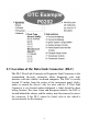
2.3 Location of the Data Link Connector (DLC) The DLC (Data Link Connector or Diagnostic Link Connector) is the standardized 16-cavity connector where diagnostic scan tools interface with the vehicle's on-board computer. The DLC is usually located 12 inches from the center of the instrument panel (dash), under or around the driver’s side for most vehicles. If Data Link Connector is not located under dashboard, a label should be there telling location.
2.4 OBD II Readiness Monitors An important part of a vehicle’s OBD II system is the Readiness Monitors, which are indicators used to find out if all of the emissions components have been evaluated by the OBD II system. They are running periodic tests on specific systems and components to ensure that they are performing within allowable limits. Currently, there are eleven OBD II Readiness Monitors (or I/M Monitors) defined by the U.S. Environmental Protection Agency (EPA).
monitors are termed non-continuous monitors. For different ignition type engines, the available monitors are different too. The following monitors are to be used for spark ignition engines only: 1) 2) 3) 4) 5) 6) 7) EGR System O2 Sensors Catalyst Evaporative System O2 Sensor Heater Secondary air Heated Catalyst The following monitors are to be used for compression ignition engines only: 1) 2) 3) 4) 5) 6) EGR System NMHC Catalyst NOx aftertreatment Boost pressure system Exhaust gas sensor PM filter 2.
including erasing of diagnostic trouble codes (DTCs) with a scan tool or a disconnected battery, can result in Readiness Monitors being set to “Not Ready”. Since the three continuous monitors are constantly evaluating, they will be reported as “Ready” all of the time. If testing of a particular supported non-continuous monitor has not been completed, the monitor status will be reported as “Not Complete” or “Not Ready.
of the enabling criteria. Drive cycles vary among vehicles and for each monitor in any particular vehicle. OBD II Drive Cycle -- A specific mode of vehicle operation that provides conditions required to set all the readiness monitors applicable to the vehicle to the “ready” condition. The purpose of completing an OBD II drive cycle is to force the vehicle to run its onboard diagnostics.
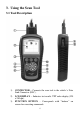
3. Using the Scan Tool 3.1 Tool Description 1) 2) 3) CONNECTOR -- Connects the scan tool to the vehicle’s Data Link Connector (DLC). LCD DISPLAY -- Indicates test results. TFT color display (320 x 240 dpi). FUNCTION BUTTON – Corresponds with “buttons” on screen for executing commands.
4) ESC BUTTON -- Cancels a selection (or action) from a menu or returns to the previous screen. 5) LEFT SCROLL BUTTON -- When look up DTC definitions, moves to previous character and views additional information on previous screens if DTC definition covers more than one screen; views previous screen or previous frames of recorded data. It is also used to view previous trouble code when viewing DTCs. 6) HELP BUTTON -- Provides help information and Code Breaker function.
3.2 Specifications 1) 2) 3) 4) 5) 6) Display: TFT color display (320 x 240 dpi) Operating Temperature: 0 to 60°C (32 to 140 °F) Storage Temperature: -20 to 70°C (-4 to 158 °F) External Power: 12.0 to 18.0 V power provided via vehicle battery or adapter. Dimensions: Length Width Height 199 mm (7.83”) 104.5 mm (4.11”) 37.5 mm (1.48”) Weight: 0.28kg(without wire) 0.484kg(with wire) 3.3 Accessories Included 1) 2) 3) 4) 5) 6) User’s Manual -- Instructions on tool operations.
2) Find DLC on vehicle. A plastic DLC cover may be found for some vehicles and you need to remove it before plugging the OBD2 cable. 3) Plug the cable to the vehicle’s DLC. 4) Power up the scan tool , and wait for the Main Screen to appear.(Figure 3.1) Figure 3.1 3.6 System Setup The System Setup functions allow you to adjust default settings and view information about the scan tool. 1) Language: Selects the desired language. 2) Unit of measure: Sets the unit of measure to English or Metric.
From the Main Screen: Use LEFT/RIGHT scroll button to select Setup, and press the OK button. Following the instructions to do adjustments and settings could make your diagnosis more conveniently and easily. (Figure 3.2) Figure 3.2 Language Setup English is the default language. 1) From System Setup screen, use the UP/DOWN scroll button and LEFT/RIGHT scroll button to select Language, and press the OK button.
Unit of Measure Metric is the default measurement unit. 1) From System Setup screen, use the LEFT/RIGHT scroll button to select EN/METRIC and press the OK button. 2) From Unit of Measure screen, use the LEFT/RIGHT scroll button to select the desired unit of measurement. (Figure 3.4 ) Figure 3.4 3) Press the OK button to save your selection and return to previous menu. Or, press the ESC button to exit without saving. Beep Set The default setting is Beep On.
Figure 3.5 Key Test The Key Test function checks if the keyboard is working properly. 1) From System Setup screen, use the UP/DOWN scroll button and LEFT/RIGHT scroll button to select Key Test, and press the OK button. 2) Press any key to start test. When you press a key, the edge around corresponding key on the screen should turn to red. Otherwise, the key is not functioning properly. 3) Double press ESC to return to previous menu.
About The About function allows viewing of some important information such as serial number and software version number of the scanner. 1) From System Setup screen, use the UP/DOWN scroll button and LEFT/RIGHT scroll button to select About and press the OK button; wait for the About screen to appear. 2) View tool information on screen. (Figure 3.6) Press the ESC button to exit without saving. Figure 3.6 3.
For your vehicle to be OBD II compliant it must have a 16-pin DLC (Data Link Connector) under the dash and the Vehicle Emission Control Information Label must state that the vehicle is OBD II compliant. 3.8 Product Troubleshooting Vehicle Linking Error A communication error occurs if the scan tool fails to communicate with the vehicle’s ECU (Engine Control Unit). You need to do the following to check up: Verify that the ignition is ON.
4. Playback Data The Playback Data function allows viewing data from last test recorded by the scan tool. 4.1 Reviewing Data 1) Use the UP/DOWN scroll button and LEFT/RIGHT scroll button to select Playback from Main Screen (Figure 3.1), and press the OK button. Wait for the Review data screen to appear. Review data 1.EPB 2.Scan Figure 4.1 2) To review data saved in the scan function, select Scan in the Review data menu. To review data saved in the EPB function, select EPB in the Review data menu.
If no data from previously tested vehicle is recorded, a message “No data available!” shows on the screen. 4) Review selected data on screen. Vehicle Specification Vehicle: Mustang Engine Type: Other Capacity: 3.8L Transmission: Manual Fuel Type: Gasoline Emission Level: Federal Emission VIN:1FAFP40462F100819 PrefSuf:2R3APB VersionID:4612 Print Figure 4.3 4.2 Deleting Data By selecting Delete on the Scan/ EPB screen, you are allowed to erase the selected data on the scan tool.
5. OBDII Diagnostics The OBD II Diagnostics function is a fast-access option that allows you to carry out a quick test on the engine system of OBD II vehicles. When more than one vehicle control module is detected by the scan tool, you will be prompted to select the module where the data may be retrieved. The most often to be selected are the Power-train Control Module [PCM] and Transmission Control Module [TCM]. CAUTION: Don’t connect or disconnect any test equipment with ignition on or engine running.
the vehicle. Contact your local distributor or the manufacturer’s customer service department for assistance. 7) View a summary of system status (MIL status, DTC counts, Monitor status) on screen. (Figure 5.1 ) Press ESC button for Diagnostic Menu (Figure 5.3) to come up. System Status MIL Status Codes Found Monitors N/A Monitors OK Monitors INC OFF 0 8 2 0 Save OK Figure 5.1 If more than one module is detected, you will be prompted to select a module before testing. (Figure 5.
more than a specified amount of key-cycles. These codes will cause the control module to illuminate the malfunction indicator light (MIL) when emission-related fault occurs. Pending Codes are also referred to as “maturing codes” or “continuous monitor codes”. They indicate problems that the control module has detected during the current or last driving cycle but are not considered serious yet. Pending Codes will not turn on the malfunction indicator lamp (MIL).
Read Codes 1.Stored Codes 2.Pending Codes 3.Permanent Codes Figure 5.4 If there is not any Diagnostic Trouble Code, the display indicates “No (pending) codes are stored in the module!” Wait a few seconds or press any key to return to previous screen. NOTE: Permanent Codes function is available for merely vehicles supporting the CAN protocols. 3) View DTCs and their definitions on screen. 4) If more than one DTC is found, use the UP/DOWN scroll button to check all the codes.
If the manufacturer of your vehicle is not listed, use the UP/DOWN scroll button to select Other and press the OK button. 5.2 Erase Codes CAUTION: Erasing the Diagnostic Trouble Codes may allow the scan tool to delete not only the codes from the vehicle’s on-board computer, but also “Freeze Frame” data and manufacturer specific enhanced data. Further, the I/M Readiness Monitor Status for all vehicle monitors is reset to Not Ready or Not Complete status.
Erase Codes DTCs and Freeze Data will be lost Do you wish to continue? Yes No . Figure 5.7 If you do not want to proceed with erasing codes, press ESC button or select NO to exit and return to previous screen. 3) Press the OK button to confirm. If the codes are cleared successfully, an “Erase Done!” confirmation message shows on the display.( Figure 5.7) Erase Codes Erase Done! Press any key to continue . Figure 5.7 If the codes are not cleared, then an “Erase Failure.
4) Press any button to return to Diagnostic Menu. 5.3 Live Data In this function, you can not only read the live data but also record data for later review. Viewing Data The View Data function allows viewing of live or real time PID data of vehicle’s computer module(s). 1) To view live data, use the UP/DOWN scroll button to select Live Data from Diagnostic Menu and press the OK button. (Figure 5.3) 2) Wait a few seconds while the scan tool validates the PID MAP. (Figure 5.9) Live Data Reading PID.
…………………Live Data . 1. Complete List 2. Custom List Figure 5.10 2) View live PIDs on the screen. Use the UP/DOWN scroll button for more PIDs if additional information is available on more than one page.( Figure 5.11) Complete List Numbers of DTCs Fuel system 1 status Fuel system 2 status Calculated load value Engine coolant temperature Pause 0 OL -0.0 -40 Graphics % 0 C Save Figure 5.11 If the “Graphics” on the bottom appears when a PID is highlighted, graphic information is available.
Figure 5.12 If the “Merge Graph” on the bottom appears when a PID is selected to view, merged graph information is available. (Figure 5.13) NOTE: Merge Graph can be used to compare two related parameters in graphic mode, which is especially convenient in the Custom List option where you could select two interacted parameter to merge and see their relationship. Figure 5.13 Select Text to return to text viewing of PID data. Select Save to record retrieved live data and PID graphs.
Select Pause to suspend viewing. You could resume the viewing process again by selecting Start. 3) Press the ESC button to return to previous menu. B. Viewing Custom List 1) To view customized PID data, use the UP/DOWN scroll button to select Custom List from Live Data menu and press the OK button.( Figure 5.10) 2) Use the UP/DOWN scroll button to move up and down to the desired items and click Select button to confirm. The selected parameters are marked with solid squares.( Figure 5.14 ) ………… ..
Custom List Numbers of DTCs Fuel system 1 status Pause 0 OL Graphics Save Figure 5.15 4) Use the ESC button to return to previous menu. Recording Data The Record Data function allows recording vehicle modules’ Parameter Identification (PID) data to help diagnose intermittent vehicle problems. You could save data files to the SD card and then use the Playback function to view the saved files. NOTE: The length of time for each frame varies per vehicle.
If you record live data under graph mode, following screen shows: Figure 5.17 NOTE: The scan tool can only playback text data even though the data is saved in graphic mode. 2) When there is not enough memory space, a warning message prompting to delete previously recorded data. Save Failure Memory space not enough! Erase previously recorded Data? Yes No Figure 5.18 If you wish to delete the data, select Yes and save currently retrieved data in the SD card.
3) Select Pause to suspend recording. You could resume the recording process again by selecting Start. 4) You may review the saved data in Playback function. 5) Press ESC button to exit. 5.4 Freeze Frame Freeze Frame Data allows the technician to view the vehicle’s operating parameters at the moment a DTC (Diagnostic Trouble Code) is detected. For example, the parameters may include engine speed (RPM), engine coolant temperature (ECT), or vehicle speed sensor (VSS) etc.
4) Select Save to record freeze frame. A confirming message “Save success!” shows on the display and scan tool return to previous menu. 5) If you don’t want to save the freeze frame data, press ESC button to return to previous screen. 5.5 Retrieving I/M Readiness Status I/M Readiness function is used to check the operations of the Emission System on OBD2 compliant vehicles. It is an excellent function to use prior to having a vehicle inspected for compliance to a state emissions program.
1) Use the UP/DOWN scroll button to select I/M Readiness from Diagnostic Menu and press OK button. (Figure 5.3) 2) Wait a few seconds while the scan tool validates the PID MAP. 3) If the vehicle supports both types of tests, then both types will be shown on the screen for selection. (Figure 5.20) …………… I/M Readiness . 1.Since DTCs Cleared 2.This Drive Cycle Figure 5.
FUEL -- Fuel System Monitor CCM -- Comprehensive Component Monitor EGR – EGR System Monitor HCCAT -- NMHC Catalyst Monitor NCAT -- NOx Aftertreatment Monitor BP -- Boost Pressure System Monitor EGS -- Exhaust Gas Sensor Monitor PM -- PM Filter Monitor Since DTCs cleared MIL Status Misfire Monitoring Fuel system monitoring Comprehensive component monitoring Catalyst monitoring Heated catalyst monitor OFF N/A OK OK N/A N/A Figure 5.
7) Press the ESC button to return to Diagnostic Menu. 5.6 O2 Monitor Test OBD2 regulations set by SAE require that relevant vehicles monitor and tests on the oxygen (O2) sensors to identify problems related to fuel efficiency and vehicle emissions. These tests are not on-demand tests and they are done automatically when engine operating conditions are within specified limits. These test results are saved in the on-board computer's memory.
…………….O2 Monitor Test………….. The selected mode is not supported! Press any key to continue . Figure 5.24 4) View test results of selected O2 sensor. (Figure 5.25) … ……… .O2 Bank1 Sensor2 . Rich-Lean Threshd V Lean-Rich Threshd V Low for Switch (V) High for Switch (V) Rich-Lean Threshd S Lean-Rich Threshd S Figure 5.25 5) 6) Use the UP/DOWN scroll button to view more screens of data if additional information is available in more than one page. Press the ESC button to return to the previous menu. 5.
and a current value for each monitor. By comparing the current value with the minimum and maximum value, the scan tool will determine if it is OK. 1) Use the UP/DOWN scroll button to select On-Board Monitor Test from Diagnostic Menu and press the OK button. (Figure 5.3) 2) Wait a few seconds while the scan tool validates the PID MAP. 3) The scan tool will prompt you to select the vehicle make.
If the vehicle under test does not support the mode, an advisory message will be displayed on the screen. (Figure 5.28) On-Board Monitor Test The selected mode is not supported Press any key to continue Figure 5.28 For CAN-equipped vehicles, test selections can be as below: On-Board Monitor Test .. 1. EGR Monitor 2. Mis-Fire Monitor Data 3. Mis-Fire Cylinder 1 Data 4. Mis-Fire Cylinder 2 Data 5. Mis-Fire Cylinder 3 Data 6. Mis-Fire Cylinder 4 Data Figure 5.
For CAN-equipped vehicles, test results displayed can be as below: Flow Test ID Module Test Value Min Limit Max Limit Status 11 $10 0.10 0.00 95.0 OK % % % Figure 5.30 8) Press ESC button to return to the previous menus. 5.8 Component Test The Component Test function allows initiating a leak test for the vehicle's EVAP system. The scan tool itself does not perform the leak test, but commands the vehicle's on-board computer to start the test.
3) If the test has been initiated by the vehicle, a confirmation message will be displayed on the screen. Component Test Command Sent! Press any key to continue Figure 5.33 Some vehicles do not allow scan tools to control vehicle systems or components. If the vehicle under test does not support the EVAP Leak Test, an advisory message is displayed on the screen. .............Component Test The selected mode is not supported Press any key to continue Figure 5.
2) An advisory message comes up to remind you. Wait a few seconds or press any key to continue. Vehicle Info. Turn key on with engine off ! Press any key to continue Figure 5.35 3) Wait for the scan tool to display the Vehicle Info. menu. Vehicle Info. 1.Vehicle ID Number 2.Caibration ID 3.Cal. Verf. Number Figure 5.36 If the vehicle does not support this mode, a message shows on the display warning that the mode is not supported. 4) From Vehicle Info.
Vehicle ID Number VIN 1FAFP40462F100819 Esc Figure 5.37 6) Press the ESC button to return previous menu 5.10 Modules Present The Modules Present function allows viewing of the module IDs and communication protocols for OBD2 modules in the vehicle. 1) Use the UP/DOWN scroll button to select Modules Present from Diagnostic Menu and press OK button. (Figure 5.3) 2) View modules present with their IDs and communication protocols. Modules Present Protocol SAE J1850 PWM ID $10 Save Figure 5.
5.11 DTC Lookup The DTC Lookup function allows user to search definitions of DTC stored in built-in DTC library. 1) Use the UP/DOWN scroll button to select DTC Lookup from Diagnostic Menu and press OK button. (Figure 5.3) 2) Wait for the scan tool to display the DTC Lookup screen. DTC Lookup Only PCBU can be the first letter to be put in. Only 0~9,a~f for the rest letters... Finish Show Esc Figure 5.39 3) Select Show and a soft keyboard will pop up.
Trouble Codes P0005 Fuel Shutoff Valve A Control Circuit/Open Save Figure 5.41 Use the LEFT/RIGHT scroll button to view the previous / next DTC. Select Save to record code definition. For manufacturer specific codes, you need to select a vehicle make on an additional screen to look for DTC definitions. If definition could not be found (SAE or Manufacturer Specific), the scan tool displays “Please refer to vehicle service manual!” 6) Press No or ESC button to return to previous menu.
6. Print and Update 6.1. Print Data The Print Data function allows printing out diagnostic data recorded by the scan tool or customized test reports by connecting the scan tool to a PC or laptop with the USB cable supplied. To print out retrieved data, you need the following tools: MaxiService®EBS301 scan tool A PC or laptop with USB ports A USB cable 1) Install PC Suit through the included CD, or download the applications in our website: www.auteltech.com or our distributors’ site.
6) The selected data will display on the textbox of Printer. By selecting the function keys on the right, you could execute the following operations: Print – Print all data in the textbox to a printer connected to your computer. Edit – Once clicked, the software will automatically open an NOTEPAD window with all recorded data showing on. Copy – Copy all data in the textbox to the clipboard. Clear – Delete all data in the textbox. Exit – Quit the operation.
select User Register. Or, Click on the Updates column in the lower right corner of the screen, and select Register. 3. The screen of Register Information appears. Please read through the instructions, and click on Agree to continue. 4. Put in the Product Serial No. and Register Password, and click on Next. (Figure 6.2) 5. Follow the instructions on screen to finish the registration. NOTE: Please use the About function to find out the Product Serial No. and Register Password.
3. Remove the Micro SD card from the scan tool. 4. Connect the Micro SD card to computer with a card reader. 5. Run the update option in PC Suit software. Wait for the Log In window to pop up. (Figure 6.3) Figure 6.3 6. Put in the user name and password and wait for the Update window to display. If you forget your password unintentionally, you may always click the [Forget your password?] to link to our website and find your password back. 7.
Batch updating Select the programs that you would update by clicking on the check boxes next to those items. Then click the Update Selected Items button on the right side of screen. Or, click on the SELECT ALL checkbox on the right side of screen and all updatable items will be selected automatically. Then click the Update Selected Items button on the right side of screen. Check the updating process by observing the upper left progress bar [downloading] and upper right progress bar [installing].
line again. The progress will resume from the break point. When the downloading is completed, the downloaded program will be installed automatically. The new version will replace the old version. 8. Insert the Micro SD card into the scan tool, and restart the scan tool to finish the whole update.
The deleted program will automatically add to the end of program list in the UPDATE page in case you would like to install again. Theoretically, all programs in latest versions will be automatically compatible with the older versions, but if your scan tool do have a compatible problem and want to retrieve the older version for some programs, you may need to delete them first then install the older version again. Choose older version from the pull-down menu of program version. Figure 6.
7. EPB This electrical parking brake (EPB) function has a multitude of uses to maintain the electronic braking systems safely and effectively. The applications include deactivating/activating the brake control system, assisting with brake fluid control, brake diagnostics, opening and closing brake pads, setting brakes after disc or pad replacement and also reading and clearing EPB/SBC trouble codes. It is also capable of retrieving Fault Codes information from the ECU. 7.1.
3) Connect the tool to vehicle and power on. 4) Turn the ignition on. 5) Select EPB icon in the Main Screen (Figure 3.1) and wait for the vehicle manufacturer screen. Choose the correct vehicle make. (Take BENZ as an example) Figure 7.1 6) After you have selected the vehicle make (BENZ), the electrical parking brake system screen will display as below. 1. 2. 3. 4. 5. Diag. Menu Read Codes Erase Codes Live Data Active Test ECU Information Figure 7.
8) In the Diag. Menu screen, use the UP/DOWN button to select Active Test, and press the OK button. Active Test 1.Installation position of brake cables 2.Operate parking brake . Figure 7.3 A. Installation position of brake cables This function allows you to adjust the brake cables safely. After you select this function, the tool will prompt you a safety message.
Installation position of brake cable The actuation can be activated using the following function key Operating statuses Electronic parking brake Released ON . B. Figure 7.5 Operate parking brake This function allows you to deactivate or reactivate the electronic brake systems. After you select this function, the tool will prompt you a safety message. Operate parking brake Test 1. 2. 3. prerequisites: Switch on ignition Vehicle stationary. Selector lever in position P. OK . Cancel Figure 7.
By selecting Operate/Release function key, you can do the electronic parking brake system service safely and easily. Operate parking brake Operating statuses Electronic parking brake Operate Mode Electronic parking brake Vehicle stationary Operating statuses Electronic parking brake Released Release Operate . . Figure 7.8 If the vehicle being tested is not stationary on the ground, this test could not be carried out, and the tool displays a warning message.
8. Warranty and Service 8.1. Limited One Year Warranty Autel warrants to its customers that this product will be free from all defects in materials and workmanship for a period of one (1) year from the date of the original purchase, subject to the following terms and conditions: 1) The sole responsibility of Autel under the Warranty is limited to either the repair or, at the option of Autel, replacement of the scan tool at no charge with Proof of Purchase. The sales receipt may be used for this purpose.