Trademarks Autel®, MaxiSys®, MaxiDAS®, MaxiScan®, MaxiTPMS®, MaxiRecorder®, MaxiCheck® and MaxiScopeTM are trademarks of Autel Intelligent Technology Corp., Ltd., registered in China, the United States and other countries. All other marks are trademarks or registered trademarks of their respective holders.
Safety Information For your own safety and the safety of others, and to prevent possible electrical shock, fire, or damage to the device, your computer or the MaxiSys tablet on which it is applied, it is important that the safety instructions herein presented throughout this manual be read and understood by all persons operating, or coming into contact with, the device. Before using the device, always refer to and follow the safety messages.
Safety Messages Safety messages are provided to help prevent personal injury and equipment damage. All safety messages are introduced by a signal word indicating the hazard level. DANGER: Indicates conditions or practices that could result in death or serious injury to the operator or to bystanders. WARNING: Indicates conditions or practices that could result in damage to the product or equipment to which it is connected. Safety Instructions The safety messages herein cover situations Autel is aware of.
measurement purposes only. The oscilloscope does not have a protective safety ground. Do not connect the ground input (chassis) to any electrical power source. To prevent personal injury or death, use a voltmeter to check that there is no significant AC or DC voltage between the oscilloscope ground and the point to which you intend to connect it. WARNING: Applying a voltage to the ground input is likely to cause permanent damage to the oscilloscope, the attached computer, and other equipment.
damaged in any way, and stop use immediately if you are concerned by any abnormal operations. WARNING: Do not tamper with or disassemble the oscilloscope, connectors or accessories. Internal damage will affect performance. Do not block any of the instrument’s air vents as overheating will cause damage to the oscilloscope. When cleaning the oscilloscope, use wet soft cloth with mild detergent in water.
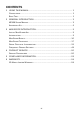
CONTENTS 1 USING THIS MANUAL ............................................................................. 1 CONVENTIONS ........................................................................................... 1 BOLD TEXT ................................................................................................ 1 2 GENERAL INTRODUCTION .................................................................... 3 MP408 SCOPE MODULE ...........................................................................
1 Using This Manual This manual contains device usage instructions. Some illustrations shown in this manual may contain features and optional equipment that are not included on your system. Contact your sales representative for availability of other features and optional tools or accessories. Conventions The following conventions are used. Bold Text Bold text is used to highlight selectable items such as buttons and menu options. Example: Click OK.
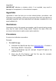
Important IMPORTANT indicates a situation which, if not avoided, may result in damage to the equipment, or the attached computer. Hyperlinks Hyperlinks or links that take you to other related articles, procedures, and illustrations are available in electronic documents. Blue italic text indicates a selectable hyperlink and blue underlined text indicates a website link or an email address link.
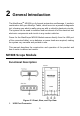
2 General Introduction The MaxiScopeTM MP408 is a 4-channel automotive oscilloscope. It works in combination with your MaxiSys Tablet, which turns into a powerful diagnostic tool, showing you what is really going on with a vehicle’s electronic circuits. The system can be used to measure and test almost all of the electrical and electronic components and circuits in any modern vehicles.
2. Input Channel A/B/C/D 3. LED Breath Light – lights up when powered on, blinks when communicating, and shimmers when error occurs 4. Warning Triangle – indicates potential safety hazard that exists on the indicated connections, and appropriate precautions should be taken. Make sure you read through the Safety Information before using. 5. Equipotential Symbol – indicates the outer shells of the indicated BNC connectors are all at the same potential.
Overload Protection ±200V on single input Maximum Sampling Rate (Single Shot) 1 and 2, or 3 and 4 channels in use 20MS/s* 1 and 3 or 4, 2 and 3 or 4 channels in use 80MS/s Buffer Memory 32M samples shared among active channels Waveform Buffer Up to 1000 waveforms Timebase Ranges 100ns/div to 1000s/div Advanced Features Math channels, Measurements Triggers Description Source Any input channel Basic Triggers Auto, Repeat, Single, None Advanced Triggers Rising edge, Falling edge Environme
NOTE*: Reduced to 20MS/s if channels A and B, or C and D, are enabled. Accessory Kit Supplied Accessories The table below gives descriptions of the hardware and accessories supplied with the package. Figure 2-3 Supplied Accessories Image Description & Quantity 1.5m USB Cable - X1 Connects the Scope Module to the computer. 3m (10ft) Screened Test Leads - X4 BNC to 4mm. Connects the Scope Module to a test probe. Screened to keep out electrical interference.
Image Description & Quantity Acupuncture Probe Set - X1 For back-probing connectors without cutting or piercing the insulation. Accepts 4mm plugs. Multimeter Probes – X1 Pair For making voltage measurements. Accepts 4mm plugs. Supported Accessories The table below gives descriptions of additional accessories supported by the MaxiScope. If any of them is needed, please purchase by yourself.
60MHz High-speed Probe For accurate measurement of fast signals like CAN bus and FlexRay. Standard BNC plug. Fuse Extension Lead (20A/30A) In both mini and standard sizes. Plug the original fuse into the lead; plug the lead in the fuse socket, then use a current clamp to measure fuse current.
3 MaxiScope Introduction This section focuses on the instructions of using the MaxiScope with an Android tablet (only for some of Autel tools). Make sure to install the MaxiScope app before connecting the scope module for the first time. Some illustrations shown in this manual may contain options or functions that are not included on your system. Contact your sales representative for availability of these features.
signals. Below is the layout of the MaxiScope main screen, other functions will be described in the following sections Figure 3-1 MaxiScope App Main Screen MaxiScope Basics Connection Status Icon If the MaxiScope is connected to the tablet, a green check will display on the bottom of the Scope icon on the top right of the screen. Otherwise, a red cross displays.
Figure 3-2 MaxiScope Connected Figure 3-3 MaxiScope Disconnected MaxiScope View Mode Normal Mode In Normal Mode, waveforms are captured when the time base is shorter than 200ms/div, and incontinuous between screens.
Continuous Mode In Continuous Mode, waveforms are captured when the time base is longer than 200ms/div, and continuous between screens. Figure 3-4 Normal Mode Figure 3-5 Continuous Mode From the views displayed on Figure 3-5, we can know that in Continuous Mode, the data displays on one screen is actually captured in multiple phases.
MaxiScope Channel Status Bar It shows the ON/OFF status of each channel. Every channel displays in a unique color. The screenshot below shows the views with four channels open.
Channel settings: Change channel settings including Amplitude, Probe and AC/DC settings. Amplitude range: Set the coordinate range of Y-axis, see in the image below. AC/DC: Alternative current/direct current, see in the image below. Probe zoom scale: Set the scale based on the specific probe being used. Long press to open the Probe Settings. Trigger Setting Bar Figure 3-8 Trigger Settings Trigger: Used to filter and capture the specified waveform data.
4) Single: Stop to capture data once one waveform is captured. Trigger threshold: The amplitude of the trigger point. Trigger edge: Includes Rise and Fall. 1) Rise: Waveform is triggered on Rise edge. 2) Fall: Waveform is triggered on Fall edge. Measurement Rulers Figure 3-9 Measurement Rulers Amplitude ruler: Used to measure relative or absolute signals. Time ruler: Used to measure relative or absolute time. File Save as PDF: Save as PDF file. Save as text: Save as txt file.
Figure 3-10 File Tools Help About: Used to check the hardware version number and software version number and other information about the device. Check update: Provides software and firmware update. Connect to the internet to check if new updates are available.
Figure 3-12 About MaxiScope Functions Data Collection Mode Normal Mode It is used to connect to the signal source to capture hardware data and view and waveform. When there is no input signal, the software shows as below.
Figure 3-13 Normal Mode Demo Mode It allows user to use MaxiScope for demonstration when no signal source is connection. The following image shows the status when no signal source is connected.
Auto Setup Click it to set the range of X-axis and Y-axis, and generally waveforms of 3 to 5 periods will display. The range of X-axis and Y-axis will be set at the same time, and time base and amplitude can be set manually for waveform viewing.
Start/Stop Start: Click it to start data collection. Stop: Click it to stop data collection. Figure 3-17 Start Screen Figure 3-18 Stop Screen Time Base The time for collect one measurement unit of data. Normal mode: The time base is shorter than 200ms/div. Continuous mode: The time base is longer than 200ms/div.
Figure 3-19 Time Base Selection Waveform Cache It is used to view the waveform records.
View Mode Oscilloscope Mode It is used with Time Base to set the time of data collection to capture waveform data. Figure 3-21 Oscilloscope Mode Spectrum Mode It is used with Current Data Collection Frequency to set the frequency and quantity of data collection.
Figure 3-22 Spectrum Mode Trigger Function Trigger: It is used to filter and capture specified waveform data (Figure 3-20). The position of the trigger point can be modified by changing the trigger threshold or the trigger time. Trigger source (channel), trigger mode, trigger direction, trigger type and trigger threshold can be set by clicking the trigger mode.
Figure 3-24 Trigger Mode Setting 2 Measurement It is used to calculate the parameters in the currently captured signal and display the signal graph in digitals. As shown in the image below, at most 5 measurements can be displayed at the same time.
Table 3-1 Measurements Measurements Maximum The highest level reached by the signal. Minimum The lowest level reached by the signal. Peak to Peak The difference between Maximum and Minimum. AC RMS The root mean square (RMS) value of the waveform minus the DC Average. True (RMS) The root mean square (RMS) value of the waveform, including the DC component. Cycle Time The time of a signal cycle. DC Average The mean value of the waveform.
X@Min The value on the X-axis when the signal on Y-axis reaches to the minimum value. Positive Acreage The acreage of waveform above the zero reference in N full-cycle waveforms displayed on the screen. Negative Acreage The acreage of waveform below the zero reference in N full-cycle waveforms displayed on the screen.
Tap the Print button, the current screen will be printed as images. Figure 3-26 Print Settings Tap this button to select and set parameters for math channel, serial decoding and frequency domain.
Figure 3-28 Settings 2 Mathematic Calculation Math Channel: Operates some basic calculations on the captured data. Currently, only the data from Channel A and B can be processed and at most 4 calculations can be conducted at the same time.
Figure 3-30 Mathematic Calculation 2 NOTE Currently, Sqrt, Abs, Sin, Cos and Tan only support calculations on Channel A data. Serial Decoding Decode data from a serial bus, including CAN, LIN, FlexRay, UART/RS232, I2C, SPI, I2S and USB.
Decoding setting dialog contains three parts: protocol, protocol settings and display setting. Protocol: There are three options in this table: Channel, Protocol and Enable. Protocol settings: Set Baud Rate (protocol related), Threshold (for distinguishing high and low electrical levels) and Advanced Settings (protocol related) in this section. Display settings: Set display format of data in the table.
Figure 3-33 Protocol Settings 2 Serial Protocol Introduction CAN Protocol CAN (Controller Area Network) is a serial protocol used in automotive and industrial machinery, which allows microcontrollers communicating with each other. MaxiScope can decode CAN_H and CAN_L signals. Threshold: It is the median between high and low logical electrical levels. It is recommended to set the waveform median as the threshold, or manually adjust this value according to actual condition.
Figure 3-34 CAN Protocol Settings 1 Figure 3-35 CAN Protocol Settings 2 CAN Protocol Data List Number (No.): The serial number of frames (decimal). It indicates the CAN protocol frame number that currently decoded. Frame ID: Identifier (hexadecimal). It is unique for specific data type, the base frame has an 11-bit identifier, and the extended frame has a 29-bit identifier. RTR: Remote transfer request. SRR: Used only in extended frame. IDE: Extended frame identifier. R0: Reserved bit.
DLC: Data length code. It indicates the number of data bytes. Data byte: Data content of the packet, DLC byte length (hexadecimal). CRC sequence: Data cyclic redundancy check (hexadecimal). CRC delimiter: The fixed bit after the CRC sequence field. ACK: Node asserts this bit to acknowledge receipt. ACK delimiter: The fixed bit after ACK field. Start time: The value of the time base when the frame starts. End time: The value of the time base when the frame ends.
Figure 3-37 LIN Protocol Settings 2 LIN Protocol Data List Number (No.): The serial number of frames (decimal). It indicates the LIN protocol frame number that currently decoded. Break: An indicator for frame starting. Sync: A fixed value (0x55) used for automatic baud rate detection. Frame ID: Six-bit value of the data type carried by the identification frame. Data count: The number of bytes of the data in the frame. Data byte: The data content of the packet.
Figure 3-38 FlexRay Protocol Settings 1 Figure 3-39 FlexRay Protocol Settings 2 FlexRay Protocol Data List Number (No.): The serial number of frames (decimal). It indicates the FlexRay protocol frame number that currently decoded. TSS: Transmission starting signal. The frame is bit 0. FSS: Frame starting signal. The frame is bit 1. BSS: Byte starting signal. It is a fixed 2-bit code. Reserved bit: Undefined. Payload preamble indicator: Indicates the presence of a network management vector or message ID.
Sync frame indicator: Indicates whether the frame is a synchronization frame. Frame ID: Defines the slot in which the frame is transmitted. Payload length: The number of payload bytes divided by 2. Header CRC: Cyclic redundancy check of data from the sync frame indicator to the payload length. Cycle count: Cycler counter. Payload: 0-254 bytes of the data. Payload CRC: Frame CRC. FES: Frame ending signal. Start time: The value of the time base when the frame starts.
Figure 3-40 UART/RS232 Protocol Settings 1 Figure 3-41 UART/RS232 Protocol Settings 2 UART/RS232 Protocol Data List Number (No.): The serial number of frames (decimal). It indicates the UART/RS232 protocol frame number that currently decoded. Packet: All packet in this form are classified as data. Start bit: A fixed bit of 1-bit. Data byte: The content of the packet. Parity byte: Error-checking bit at the end of the byte (if available). End byte: 1-2 bits at the end of the byte.
SPI Protocol SPI (Serial Peripheral Interface) bus is the serial data standard for the communications between microcontrollers and peripherals. It originally used 4-line links, 3-line and 2-line links are also in application, MaxiScope uses 3-line link to analyze this protocol. CLK: Indicates the channel connected to clock signal. Clock threshold: Used to distinguish the voltage values between high and low logic electrical levels of the clock signal. DATA: Indicates the channel connected to data signal.
Figure 3-43 SPI Protocol Settings 2 SPI Protocol Data List Number (No.): The serial number of frames (decimal). It indicates the SPI protocol frame number that currently decoded. Packet: Packet types: start, end, address, data and undefined. Start bit: The content of the packet. Start time: The value of the time base when the frame starts. End time: The value of the time base when the frame ends.
WS threshold: Used to distinguish the voltage values between high and low logic electrical levels of the chip select (WS) signal. Figure 3-44 I2S Protocol Settings 1 Figure 3-45 I2S Protocol Settings 2 I2S Protocol Data List Number (No.): The serial number of frames (decimal). It indicates the I 2S protocol frame number that currently decoded. Packet: All packet in this form are classified as data. Start bit: The content of the packet. Start time: The value of the time base when the frame starts.
I2C Protocol I2C (Inter-Integrated Circuit) is a serial protocol used in consumer electronics for communications between components on the same electric board and between computers and monitors. It uses two signals: clock (SCL) and data (SDA). SCL: Indicates the channel connected to clock signal. Clock threshold: Used to distinguish the voltage values between high and low logic electrical levels of the clock signal. SDA: Indicates the channel connected to data signal.
I2C Protocol Data List Number (No.): The serial number of frames (decimal). It indicates the I2C protocol frame number that currently decoded. Packet: Packet types: start, end, address, data and undefined. Address: Shown for address packets. R/W: Polarity of the read/write flag. Data byte: The content of the packet. ACK: Whether the address confirms the packet. Start time: The value of the time base when the frame starts. End time: The value of the time base when the frame ends.
Figure 3-48 USB Protocol Settings 1 Figure 3-49 USB Protocol Settings 2 USB Protocol Data List Number (No.): The serial number of frames (decimal). It indicates the USB protocol frame number that currently decoded. Sync: An 8-bit preamble for each data packet to synchronize the packet transmission rate of the USB device with the bus. The value has a fixed bit 00000001.
PID field: Used to indicate the packet type, including token, data, handshake and special. Data field: Used to carry the information to be transited between the host and the device. The content and length vary by identifier and transmission type. In the USB packet, the data segment may contain the device address, endpoint number, frame serial number, data and other content. CRC: The number of bits in CRC data vary by packet type. Important data uses CRC16 data field while others use CRC5.
the number of samples in the source waveform. If the source waveform contains fewer samples that required (that is, fewer than twice the number of the frequency bins), then MaxiSope will zero-pads the waveform up to the next power of two. For example, if the scope view contains 10,000 samples, and you set Spectrum Bins to 16,384, then MaxiScope zero-pads the waveform to 16,384 samples, which is the nearest power of two above 10,000.
BlackmanHarris 1.90 -92 6 General-purpose Flat-top 2.94 -44 6 Negligible pass-band ripple; used mainly for calibration Rectangul ar 0.89 -13.2 6 No fading; maximal sharpness; used for short transients Display mode: The current version only support importance. Logarithmic unit: Indicates the logarithmic unit used on Y-axis.
Figure 3-52 Spectrum Measurements Frequency at peak: The frequency at which the peak signal value appears. Amplitude at peak: The amplitude of the peak signal value. Average amplitude at peak: The amplitude of the peak signal value averaged over a number of captures. Total power: The power of the whole signal captured in the spectrum view, calculated by adding the powers in all spectrum bins. Total harmonic distortion (THD)%: The ratio of the sum of harmonic powers to the power at the fundamental frequency.
Total harmonic distortion plus noise (THD+N): The ratio of the harmonic power plus noise to the fundamental power. The THD+N values are always greater than the THD values for the same signal. THD + N = 10log10 ( THD + N ) Vf Spurious-free dynamic range (SFOR): This is the ratio of the amplitude of specific point (generally, the highest peak) in the spectrum to that of the second highest peak (it is called the SFDR frequency). SFDR frequency is not necessarily a harmonic of the fundamental frequency.
frequency rulers in the spectrum window). For reference, the third-order terms are at frequencies (2F1 + F2), (2F1 – F2), (F1 + 2F2) and (F1 – 2F2). NOTE Hanning or Blackman windows are recommended because of their low noise. An FFT size of 4096 or greater is recommended in order to provide adequate spectral resolution for the IMD measurements.
4 Product Service This section introduces information for technical support, repair service, and application for replacement or optional parts. Service Procedures This section introduces information for technical support, repair service, and application for replacement or optional parts. Technical Support If you have any question or problem on the operation of the product, please contact us. AUTEL NORTH AMERICA Phone: 855-AUTEL-US (855-288-3587) Monday-Friday 9am-6pm EST Website: www.autel.
Phone: (+507) 308-7566 Website: www.autel.com/es Email: sales.latin@autel.com, latsupport@autel.com Address: Office 103, Building 3845, International Business Park, Veracruz, Panamá Pacífico, Panamá AUTEL AUSTRALIA Phone: 03 9480 2978 / +61 476293327 Website: www.autel.com.au Email: sales@autel.com.au Address: 155 Islington Street, Melbourne, Collingwood, VIC 3066 For technical assistance in other markets, please contact your local selling agent.
Other Services You can purchase the optional accessories directly from Autel’s authorized tool suppliers, and/or your local distributor or agent.
5 Compliance Information FCC Compliance This equipment has been tested and found to comply with the limits for a Class B digital device, pursuant to Part 15 of the FCC Rules. These limits are designed to provide reasonable protection against harmful interference in a residential installation. This equipment generates uses and can radiate radio frequency energy and, if not installed and used in accordance with the instructions, may cause harmful interference to radio communications.
6 Warranty 12-Month Limited Warranty Autel Intelligent Technology Corp., Ltd.
IMPORTANT All contents of the product may be deleted during the process of repair. You should create a back-up copy of any contents of your product before delivering the product for warranty service.