Trademarks Autel®, MaxiSys®, MaxiDAS®, MaxiScan®, MaxiTPMS®, MaxiRecorder®, and MaxiCheck® are trademarks of Autel Intelligent Technology Corp., Ltd., registered in China, the United States and other countries. All other marks are trademarks or registered trademarks of their respective holders.
Safety Information To prevent personal injury or damage to vehicles and/or the scan tool, read this instruction manual first and observe the following safety precautions at a minimum whenever working on a vehicle: Always perform diagnosis or service in a safe environment. Wear safety eye protection that meets ANSI standards. Keep clothing, hair, hands, tools, test equipment, etc. away from all moving or hot engine parts.
Table of Contents 1. USING THE MANUAL ................................................................... 1 1.1 CONVENTIONS .................................................................................... 1 2. GENERAL INFORMATION ......................................................... 3 2.1 TPMS SYSTEM REVIEW...................................................................... 3 2.2 TPMS LEGISLATION ........................................................................... 3 2.
5.1 AUTO CREATE .................................................................................. 40 5.2 MANUAL CREATE ............................................................................. 50 5.3 COPY BY OBD .................................................................................. 53 5.4 COPY BY ACTIVATION ...................................................................... 53 6. RKE & RF MONITOR .................................................................. 58 7.
1. Using the Manual This manual contains device usage instructions. Some illustrations shown in this manual may contain modules and optional equipment that are not included on your system. Contact your sales representative for availability of other modules and optional tools or accessories. 1.1 Conventions The following conventions are used. Bold Text Bold emphasis is used to highlight selectable items such as buttons and menu options. Example: Tap OK.
Hyperlinks Hyperlinks, or links, that take you to other related articles, procedures, and illustrations are available in electronic documents. Blue colored text indicates a selectable hyperlink. Illustrations Illustrations used in this manual are samples, the actual testing screen may vary for each vehicle being tested. Observe the menu titles and on-screen instructions to make correct option selection.
2. General Information 2.1 TPMS System Review A tire pressure monitoring system (TPMS) is an electronic system designed to monitor the air pressure inside the pneumatic tires on various types of vehicles. TPMS report real-time tire-pressure information to the driver of the vehicle, either via a gauge, a pictogram display, or a simple low-pressure warning light. TPMS can be divided into two different types — direct (dTPMS) and indirect (iTPMS).
2.3 TPMS Tell-tale Light When diagnosing TPMS systems, you should understand what the TPMS tell-tale light means. When turning the ignition OFF to ON, the TPMS tell-tale should come on, and then go off, which indicates the system is working fine. If the light stays on, there would be a pressure problem. If the light flashes, there would be a system problem, which can range from faulty sensors to sensors on the vehicle that haven’t been learned to that vehicle. 2.
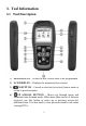
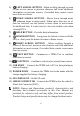
3. Tool Information 3.1 Tool Description 1) SENSOR SLOT – Holds the MX-Sensor need to be programmed. 2) LCD DISPLAY – Displays the menus and test screens. 3) N BUTTON – Cancels a selection (or action) from a menu or return to previous menu. 4) UP SCROLL BUTTON – Moves up through menu and submenu items in menu mode. When more than one set of data are retrieved, use this button to move up to previous screens for additional data. It is also used to view previous trouble code when viewing DTCs.
5) LEFT SCROLL BUTTON –When scrolling through a screen of data or text, moves to previous character and views additional information on previous screens, if recorded data content covers more than one screen. 6) DOWN SCROLL BUTTON – Moves down through menu and submenu items in menu mode. When more than one set of data are retrieved, use this button to move down to next screens for additional data. It is also used to view next trouble code when viewing DTCs. 7) HELP BUTTON – Provides help information.
3.2 Specifications 1) Display: TFT color display (320 x 240 dpi) 2) Power: 3.7 V Li-polymer battery 3) Operating Temperature: 0°C to 50°C (32°F to 122°F) 4) Storage Temperature: -20°C to 70°C (-4°F to 158°F) 5) Dimensions: Length 202.2 mm (7.96”) Width 106.7 mm (4.20”) Height 37.7 mm (1.48”) 6) Weight: 0.4 kg (0.88 lb.) 3.
1) – Indicates battery charging. 2) – Indicates there is data stored in the tool. 3) – Indicates battery volume. 4) – Indicates USB communication with the computer is established. 5) – Indicates magnet is required to activate TPMS sensor. 6) – Indicates deflation is required to activate TPMS sensor. 7) – Indicates One Wheel test mode is selected. 8) – Indicates ALL Wheels test mode is selected.
1) Locate the USB port of the device. 2) Connect the device and the computer with the USB cable. For optimum performance, always keep your tool sufficiently charged. It is recommended that you charge the tool for over 2 hours before the first use. NOTE: Only use the power adaptor or USB cable that is included in our pack to charge this tool. The use of un-approved power supplies may damage your tool and void the tool warranty. 3.
3.8 System Setting The tool allows you to make the following adjustments and settings. 1) Market: Select the area of work, Europe or America. 2) Language: Selects the desired language. 3) Pressure Unit: Sets the pressure unit in kPa, Psi or Bar. 4) Temperature Unit: Sets the temperature unit in degree Celsius or Fahrenheit. 5) Distance Unit: Sets the distance unit in Km or mile. 6) ID Format: Sets the ID displaying in Hexadecimal or Decimal. 7) Beep Set: Turns on/off key-press beep.
Figure 3.2 Market This function allows you to switch among the supported corresponding models for European and American areas. 1) From System Setting screen, use the UP/DOWN scroll button and the LEFT/RIGHT scroll button to select Market, and press the Y button. 2) From Market screen, use the LEFT/RIGHT scroll button to select the work area. 3) The tool will load the new database for the selected zone. Figure 3.3 NOTE: The Market Setting is available for Global version only.
Language English is the default language. 1) From System Setting screen, use the UP/DOWN scroll button and LEFT/RIGHT scroll button to select Language, and press the Y button. 2) Use the UP/DOWN scroll button and LEFT/RIGHT scroll button to select the desired language and press the Y button to save your selection and return to previous menu. Figure 3.
Figure 3.5 3) Press the Y button to save your settings and return to previous menu, or press the N button to exit without change. Temperature Unit 1) From System Setting screen, use the UP/DOWN scroll button and LEFT/RIGHT scroll button to select Temperature Unit, and press the Y button. 2) From Temperature Unit screen, use the LEFT/RIGHT scroll button to select the desired unit of temperature. Figure 3.
Distance Unit 1) From System Setting screen, use the UP/DOWN scroll button and LEFT/RIGHT scroll button to select Distance Unit, and press the Y button. 2) From Distance Unit screen, use the LEFT/RIGHT scroll button to select the desired unit of distance: km or mile. Figure 3.7 3) Press the Y button to save your settings and return to previous menu, or press the N button to exit without change.
Figure 3.8 3) Press the Y button to save your settings and return to previous menu, or press the N button to exit without change. Beep Set This function allows you to turn on/off the built-in speaker for key pressing. 1) From System Setting screen, use the UP/DOWN scroll button and LEFT/RIGHT scroll button to select Beep Set, and press the Y button. 2) From Beep Set menu, use the LEFT/RIGHT scroll button to select ON or OFF to turn on/off the beep. Figure 3.
Wheels This function allows you to set sensor testing mode in All Wheels or One Wheel. 1) From System Setting screen, use the UP/DOWN scroll button and LEFT/RIGHT scroll button to select Wheels, and press the Y button. 2) From Wheels screen, use the LEFT/RIGHT scroll button to select All Wheels or One Wheel mode for TPMS sensor testing. Figure 3.10 3) Press the Y button to save your selection or the N button to exit without change.
Figure 3.11 NOTE: Before the tool powers off automatically, it will save all the TPMS test data. Next time when the tool is powered on, you may retrieve the recorded data or return to the last operation. NOTE: When using external power, the scan tool stays on until you turn it off. When using internal battery power, the scan tool turns off automatically after a set time of inactivity. Date This function allows setting the date information of the tool.
About This function allows viewing of some important information such as serial number and software version number of the tool. 1) From System Setting screen, use the UP/DOWN scroll button and LEFT/RIGHT scroll button to select About, and press the Y button; wait for the About screen to appear. 2) View tool information on screen. Press the N button to exit. Figure 3.13 NOTE: If the tool is Global version, please select the correct area under Market Setting before performing test. 3.
Verify that the vehicle is equipped with TPMS. Verify that the tool battery is sufficiently charged. Turn the ignition off and wait for about 10 seconds. Turn the ignition back to on and continue the testing. Verify the control module is not defective. Operating Error If the scan tool freezes, then an exception occurs or the vehicle’s ECU (Engine Control Unit) is too slow to respond to requests, do the following to reset the tool: Reset the scan tool.
4. TPMS Check & Diagnostics The MaxiTPMS® TS501 is a new generation TPMS diagnostic & service tool specially designed to activate all known OEM/Universal TPMS sensors, and provide users with direct access to the vehicle’s ECU through OBD II connection, thus allowing users to reprogram sensor IDs and retrieve/clear TPMS DTCs, helping technicians to quickly find out faulty TPMS and turn off MILs.
Figure 4.1 3) Observe the menu title and use UP/DOWN scroll button to select by model and year to identify the vehicle being tested. The selected vehicle is remembered by the tool when a test is commenced. Select by Model: Figure 4.
Select by Year: Figure 4.3 4) For some vehicle types an option screen will show up to let users choose between 4 Wheels and 5 Wheels test mode. Figure 4.4 Depending on the test mode (All Wheels or One Wheel), results are displayed in different manners. All Wheels Mode In this mode, a function menu screen will show up (Figure 4.5). Use the UP/DOWN and LEFT/RIGHT scroll button to select a desired wheel and press the TEST button to start sensor activation (Figure 4.6).
Figure 4.6 Figure 4.5 The tool will do TPMS test in a sequence of FL (Front Left), FR (Front Right), RR (Rear Right), LR (Rear Left) and SPARE, if the vehicle has the option for the spare. Or, you can use the UP/DOWN or LEFT/RIGHT scroll button to move to the desired wheel for testing. Place the tool alongside the valve stem, point toward the sensor location, and press the TEST button. The tool will send LF signal to trigger the sensor.
Press the Y button to read all sensor data, including sensor ID, tire pressure, temperature, battery condition and modulation. Under All Wheels mode, the tool can save up to 5 TPMS sensor data records at each time. Press the UP/DOWN or LEFT/RIGHT scroll button to turn over data screens while viewing. If more than five records are stored, the latest record will overwrite the oldest record. One Wheel Mode In this mode the screen will show as below (Figure 4.8).
Figure 4.9 Once the first sensor test is completed, the screen will remain for 3 seconds for data viewing and then automatically switch to next sensor test. Follow the same procedure for the other sensor tests. Under One Wheel mode, the tool can save up to 10 TPMS sensor data records at each time. Select the wheel icon and press Y button to view all sensors’ information. Press the UP/DOWN and LEFT/RIGHT scroll button to turn over data screens while viewing.
x Wrong Sensor Type A TPMS sensor is activated and decoded, but does not match the protocol for the Make, Model or Year that the tool was set-up for. The tool displays a message “Sensor triggered but cannot be known”. In this case, verify the Make, Model or Year or other features you have selected as well as the sensor part number that was fitted. D Duplicate ID (only checked in All Wheels mode) A sensor with a duplicate ID has been read. The tool displays a message “Sensor ID Duplicated.”.
Figure 4.11 Anytime while doing the TPMS test, pressing button allows reading the sensor make, OEM part no., and relearn information for the vehicle being tested for reference. Use the UP/DOWN scroll button to view all details if the data information covers more than one page. Figure 4.12 Sensor activation can be aborted at any time by pressing the N button. When the activation is aborted, the screen will return to the previous menu.
Figure 4.13 Figure 4.14 [Pos] – Indicates the wheel sensor position. [ID-H/D] – Shows sensor ID data. [kPa/Psi/Bar] – Indicates tire pressure. [°C/°F] – Indicates tire temperature. [BAT] – Indicates battery condition. [Mode] – Defines tire sensor working mode or status. [Modulation] – Indicates sensor signal amplitude. NOTE: Different ID format, pressure and temperature units will display at the title bar according to the device’s system setting, please refer to 3.8 System Setting for detailed instruction.
which is very convenient and useful for technicians to wake up sensors of the same vehicle. 1) Use the UP/DOWN scroll button and LEFT/RIGHT scroll button to select Latest Test from Main Menu (Figure 3.1). 2) An activation screen with the previously activated sensor information will show up (Figure 4.15). Use the UP/DOWN or LEFT/RIGHT scroll button to select the desired wheel, and press the TEST button to reactivate the sensor, or press the Y button to view all detailed sensor data (Figure 4.16). Figure 4.
Figure 4.17 4) Press the Y button to delete all test records and enter test mode. Or press the N button to reserve the previous data and check the remaining untested sensors. 4.2 TPMS Relearn This function, which provides users with quick access to the vehicle’s ECU, enables users to do TPMS diagnostics, such as reading/writing sensor IDs on vehicle ECU and reading/ clearing codes of TPMS system, and to save data for later reviews and printing.
Figure 4.18 5) The tool will display a function screen as below. Use the UP/DOWN scroll button to select the desired menu and press the Y button to continue (Figure 4.19). Figure 4.19 6) The OBD II Relearn allows user to write the IDs to the system directly without performing other procedures. 7) The Relearn Procedure allows referring to the related procedures before performing Relearn. NOTE: This menu is not available for all models.
For some vehicles users may be asked to choose the specific engine model or other features before turning to the function menu. The procedure may vary by the vehicle being tested. NOTE: In this manner, the scan tool will communicate with the vehicle being tested. If there is a linking error, a notice screen will show up. Please refer to 3.9 Product Troubleshooting for more details.
Figure 4.21 The tool will display the sensor IDs and positions for your confirmation. Press the Y button to register ID in vehicle ECU, or N button to exit. Figure 4.22 Once the sensor IDs are successfully written, a confirm screen will show up. Press any key to continue the TPMS diagnostic procedure.
Figure 4.23 NOTE: The sensor writing procedure may vary for different vehicles being serviced. Please follow the onscreen instruction and take appropriate measures and selections to complete the process. NOTE: If there are untested sensors in the vehicle, the writing ID process cannot proceed. The tool will display a warning message as below. In this case, follow the sensor check procedure to activate all sensors in vehicle and register sensor IDs again. Figure 4.
turn on. Read IDs from Vehicle 1) From TPMS Diagnosis Menu, use the UP/DOWN scroll button to select the Read IDs from Vehicle, and press the Y button (Figure 4.21). 2) The tool will display the sensor IDs and positions for your viewing. Press the Y button to save data for future review, or the N button to exit without saving. Figure 4.25 Read Codes 1) From TPMS Diagnosis Menu, use the UP/DOWN scroll button to select the Read Codes, and press the Y button (Figure 4.21).
Figure 4.26 The saved DTC and sensor data can be reviewed in Review Data, which supports easy data playback and printing. Erase Codes 1) From TPMS Diagnosis Menu, use the UP/DOWN scroll button to select the Erase Codes, and press the Y button (Figure 4.21). 2) The tool will display a warning message for your confirmation. Press the Y button to continue, or N button to exit. Figure 4.27 3) If the erase command is sent successfully, the screen will show as below (Figure 4.28).
Figure 4.28 4.3 Review Data The Review Data function allows user to view and print out saved data of the latest TPMS diagnostic recordings by the service tool. Use the UP/DOWN and LEFT/RIGHT scroll button to select Review Data from Main Screen (Figure 3.1), and wait for the review data menu to appear. Figure 4.29 NOTE: If no data from the previous TPMS diagnosis is recorded, a message “No data available!” will show on the screen.
Figure 4.30 Print -- Select this function to print out the data on screen. For detailed instructions, refer to 7.1 Print Data. Delete -- Use the RIGHT scroll button to delete the selected data. Delete All -- Use the LEFT scroll button to delete all data on the screen. NOTE: Don’t use Delete All unless you are definitely sure what you are going to proceed. 4.
the date. It also provides data entry areas for other tester and vehicle data. Figure 4.
5. TPMS Sensor Programming The Programming function allows users to program the sensor data to the MX-Sensor and replace faulty sensor with low battery life or one that is not functioning. The scan tool is easy-to-use with a proven efficiency and guaranteed accurate results. NOTE: Programming function will only work with Autel’s MX-Sensor.
Figure 5.1 3) Observe the menu option and use the UP/DOWN scroll button to select by model and year to identify the vehicle being tested. NOTE: Please pay attention to the frequency used in the vehicle. Refer to the original sensor information for the exact frequency. The selected vehicle is remembered by the tool when a test is commenced. Select by Model: Figure 5.
Select by Year: Figure 5.3 4) For some vehicles (like Chrysler), an option screen will show up allowing users to choose between 4 Wheels test and 5 Wheels test mode before accessing the activation screen. Figure 5.4 Depending on the test mode (All Wheels or One Wheel), results are displayed in different manners. All Wheels Mode 1) In this mode, use the UP/DOWN scroll button and LEFT/RIGHT scroll button to select MX-Sensor icon on the lower right corner.
Figure 5.5 NOTE: The MX-Sensor icon on the lower right corner will not appear if the TPMS Sensor Programming is not supported by the selected vehicle. 2) Use the UP/DOWN scroll button to select the wheel which needs to be programmed. Figure 5.6 3) Use the UP/DOWN scroll button to select Auto Create to create a new random sensor ID.
Figure 5.7 4) Insert the correct MX-Sensor into the sensor slot as displayed below: Figure 5.8 NOTE: Please pay attention to the MX-Sensor type displayed in the screen and insert the correct MX-Sensor. Inserting incorrect MX-Sensor will cause programming failure. 5) Press the Y button to write in the new created sensor ID to the MX-Sensor and the screen will show as below (Figure 5.9), or the N button to exit without change. If an error prompt displays (Figure 5.
Figure 5.9 Figure 5.10 If programming failed, the screen will show as below, in this case, please perform programming function again. Figure 5.11 After programming is finished, a series of beep sound will be heard and the tool will display the data details such as the sensor ID, the temperature and the battery voltage after testing the new programmed MX-Sensor.
Figure 5.12 Press OK to return to the previous screen, and a sensor mark will appear on the right side of the screen, indicating the wheel sensor has been programmed. Figure 5.13 The Programmed option is available when selecting the programmed wheel sensor. Select Programmed to reprogram the wheel sensor with the same ID if necessary.
Figure 5.14 After all required MX-Sensor is programmed, please select Write IDs to Vehicle in Relearn function, and refer to 4.2 TPMS Relearn for details. One Wheel Mode 1) In this mode, the screen will show as below. Use the UP/DOWN scroll button to select MX-Sensor icon on the lower left corner. Figure 5.15 2) Use the UP/DOWN scroll button to select Auto Create to create a new random sensor ID.
Figure 5.16 3) Insert the correct MX-Sensor into the sensor slot as displayed below: Figure 5.17 NOTE: Please pay attention to the MX-Sensor type displayed in the screen and insert the correct MX-Sensor. Inserting incorrect MX-Sensor will cause programming failure. 4) Press the Y button to write in the new created sensor ID to the MX-Sensor and the screen will show as below (Figure 5.18). If an error prompts, please keep the MX-Sensor to be programmed away from other MX-Sensor (Figure 5.19).
Figure 5.18 Figure 5.19 If programming failed, the screen will show as below. In this case, please perform programming function again. Figure 5.
ID, the temperature and the battery voltage after testing the new programmed MX-Sensor. Figure 5.21 After all required MX-Sensor is programmed, please switch to All Wheels Setting and select Write IDs to Vehicle in Relearn function, refer to 4.2 TPMS Relearn for details. 5.2 Manual Create This function allows user to manually enter sensor IDs. Users can enter the random ID or the original sensor ID, if it’s available. NOTE: Do not enter the same ID for each sensor. 1) Follow the steps in 5.
Figure 5.22 Figure 5.23 3) Use the UP/DOWN scroll button and the LEFT/RIGHT scroll button to select the character and press the TEST button to confirm. Figure 5.
character. Use the Y button to finish the input and the screen will display a message requiring the user for confirmation. Select “Yes” to save the sensor ID and continue programming or “No” to return to the previous screen. Figure 5.25 NOTE: Different sensor from manufacturer may have different ID character length limit. The scan tool will automatically recognize the OEM sensor ID character length, and prompt a message when entered character length is out of limitation. Figure 5.
5.3 Copy by OBD This function allows users to write in the saved sensor information to MX-Sensor after performing Read IDs from Vehicle in Relearn function. NOTE: This function is not available under One Wheel mode. 1) Follow the steps in 5.1 Auto Create to select MX-Sensor to enter the Programming function. The OBD mark will appear on the right side of the screen (Figure 5.27).
Figure 5.29 2) Select MX-Sensor icon and a trigger mark right side of the screen. will appear on the Figure 5.30 3) Use the UP/DOWN scroll button to select the corresponding wheel, press the Y button. 4) Select Copy by Activation, insert the correct MX-Sensor into the sensor slot, and then press the Y button to start programming the retrieved sensor information to the MX-Sensor.
Figure 5.31 One Wheel Mode 1) From the activation screen, press the TEST button to trigger the original sensor. You can use the LEFT/RIGHT button to select the specific tire to be triggered. When the information is retrieved, a series of beep sound will be heard and the sensor information will display. Figure 5.32 2) Select MX-Sensor icon and press the Y button, and then select “Copy by Activation” in the next screen.
Figure 5.33 3) Select the IDs you want to program with. Figure 5.34 NOTE: In One Wheel mode, the tool can save at most 10 triggered sensors’ information each time. Please do not use the MX-Sensors with the same ID in the same vehicle. In All Wheels mode, if you had successfully performed both the Read IDs from Vehicle function and the activation function, the screen may show as below. You can choose either Copy by Activation or Copy by OBD even the IDs are not matched.
Figure 5.35 Once programmed with Copy by Activation or Copy by OBD, the MX-Sensor can be installed in the wheel directly to be mounted on the car and the TPMS warning light will turn off without needing to write IDs to the vehicle. NOTE: For the vehicles not supported by Relearn function, please select the “Manual Create” option to enter the original sensor ID manually, or trigger the original sensor at the activation screen to get the sensor information, before programming the MX-Sensor.
6. RKE & RF Monitor Today's keyless remotes -- also known as key fobs -- make life easier. But when your key fob stops working or starts to perform sporadically, it will be particularly frustrating. Check your key fob to make sure it is in top condition so it will work when you really need it. Since a key fob is attuned to a special frequency that is only detected by the car for which it was issued, you will need to use your vehicle to test the fob.
7. Print and Update To print out retrieved data or update software, you will need the followings: TS501 tool with SD card inserted PC or laptop with USB ports USB cable 7.1 Print Data The Print Data function allows printing out TPMS DTC data recorded by the service tool by connecting the scan tool to a PC or laptop with the USB cable supplied. Note: The print function is not available in Mac-based computer for the present. 1) Install the Maxi PC Suite program to the PC.
Figure 7.1 6) The selected data will display on the textbox of Printer. By selecting the function keys on the right, you could execute the following operations: Print – Print all data in the textbox to a printer connected to your computer. Edit – Once clicked, the software will automatically open a NOTEPAD window with all recorded data showing on. Copy – Copy all data in the textbox to the clipboard. Clear – Delete all data in the textbox. Exit – Quit the operation.
User could update the scan tool ONLY after you had registered the tool on our website: www.autel.com. Then you could download software, update online, retrieve information and get warranty service. NOTE: Prior to registration, please confirm your network is working properly. 1. Visit the website http://pro.autel.com. 2. On the Sign In page, input your account ID and other information to log in, if you already have an account. 3.
(Figure 7.2). Figure 7.2 2) Enter your Autel ID and password and wait for the Update window to display. If you forget your password unintentionally, you may always click the [Forget Password?] to link to our website and get your password back. 3) In the Update window, select the items you want to install. Usually, you should install all available updates. Figure 7.
2) Click on the Select All checkbox on the right side of screen and all updatable items will be selected automatically. Then click the Update Selected Items button on the right side of screen. 3) Check the updating process by observing the upper left progress bar [Downloads] and upper right progress bar [Installs]. You may also find progress information in the Status column of updated items.
old one. 6) Once the update is complete, disconnect the tool from the computer. It is now updated and ready to go. 7) For users who choose to update by SD card, please insert the SD card into the scan tool, and switch on the TPMS tool. It’s now updated and ready to go. View or Delete Programs To view the list of installed programs or to delete an installed program, please follow these steps: 1) Click on the Installed Programs tag entry and the page will show the list of programs installed.
The deleted program will automatically add to the end of program list in the UPDATE page in case you would like to install again. 8. Compliance Information FCC COMPLIANCE FCC ID:WQ83017501601 This device complies with Part 15 of the FCC Rules and with RSS-210 of Industry Canada. Operation is subject to the following two conditions: 1. This device may not cause harmful interference. 2. This device must accept any interference received, including interference that may cause undesired operation.
RF warning statement: The device has been evaluated to meet general RF exposure requirement. The device can be used in portable exposure condition without restriction。 The term “IC” before the radio certification number only signifies that IC technical specifications were met. RoHS COMPLIANCE This device is declared to be in compliance with the European RoHS Directive 2011/65/EU.
9. Warranty and Service 9.1 Limited One Year Warranty Autel warrants to its customers that this product will be free from all defects in materials and workmanship for a period of one (1) year from the date of the original purchase, subject to the following terms and conditions: 1) The sole responsibility of Autel under the Warranty is limited to either the repair or, at the option of Autel, replacement of the TPMS tool at no charge with Proof of Purchase. The sales receipt may be used for this purpose.