Table of Contents 1. 2. 3. 4. 5. 6. 7. Safety Instructions............................................................................. 1 1.1 Work Area Safety .................................................................... 1 1.2 Electrical Safety ....................................................................... 1 1.3 Personal Safety ........................................................................ 2 Description, Specifications and Tool Components.......................... 3 2.
Safety Instructions Work Area Safety 1. Safety Instructions IMPORTANT: To prevent electric shock, fire and/or personal injury or damage, read this user’s manual first and observe the following safety instructions. 1.1 Work Area Safety Always perform automotive testing in a safe environment. Keep your work area clean and well lit. Cluttered benches and dark areas may cause accidents. Keep clothing, hair, hands, tools, test equipment, etc. away from all moving or hot engine parts.
Safety Instructions Personal Safety 1.3 Personal Safety Do not use the tool while tired or under the influence of drugs, alcohol, or medications. A moment of interruption can result in serious personal injury. Do not over-reach. Keep proper footing and balance at all times. Proper footing and balance enables better control of the tool in unexpected situations. Always wear safety eye protection that meets ANSI standards. Do not wear loose clothing or jewelry.
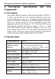
Description, Specification and Tool Components 2. Description, Components Specifications Description and Tool 2.1 Description The premier Digital Inspection Videoscope MaxiVideoTM MV201 is an ideal and powerful tool for inspecting difficult-to-reach areas normally hidden from sight. It is a completely digital platform that features the function of capturing and recording photos and videos either on its internal memory or on the removable SD cards. The ergonomic tool not only features a 3.
Description, Specification and Tool Components Specifications Recording medium Internal memory or SD card (SD card is optional and not included) Image controls Zoom, low light vision Lighting Fully adjustable LED Cable reach Imager head waterproof 1m (3') -- expandable to 6m (19') w/optional extensions 8.5mm (0.33") is standard; 16mm (0.63") and 5.5mm (0.22") are optional. Imager head and cable to 3m (10') 1 Additonal ports USB, video out and earphone ports Operating temp.
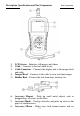
Description, Specification and Tool Components Tool Components Fig. 1 1) 2) 3) 4) 5) LCD Screen – Indicates still images and videos. Cable – Connects to the tool while in use. Cable Connector – Connects the display unit to the imager head and cable. Imager Head – Connects to the cable to view real-time images. Rubber Boot – Protects the tool from drop, abrasion, etc. 1 Fig. 2 6) 7) 8) Accessory Magnet – Picks up small metal objects such as dropped rings or screws on the floor.
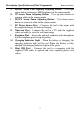
Description, Specification and Tool Components Tool Components inside the unreachable areas. 2.5 Buttons and Ports Fig. 3 A. Power Button – Turns on/off the tool. B. Setting/Back Button – Moves to the primary settings screen, while pressing again will return to the last viewed screen. C. Camera/Video Button – Helps capturing a photo while pressing again will capture a video. D. Play Button – Moves to play captured photos and videos. E.
Description, Specification and Tool Components Buttons and Ports RIGHT Arrow LED Lighting Adjusting Button – Uses right arrow button to decrease LED brightness in the camera mode. H. UP Arrow Zoom Adjusting Button – Uses up arrow button to zoom in while in the camera mode. I. DOWN Arrow Zoom Adjusting Button – Uses down arrow button to zoom out while in the camera mode. J. DC Power Source Port – Connects the tool to the mains with the supplied charger for battery charging. K.
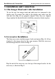
Installation and Connection The Imager Head and Cable Installation 3. Installation and Connection 3.1 The Imager Head and Cable Installation To use the tool, the imager head and cable must be connected to the display unit. To connect the cable to the display unit, make sure the key and slot (Fig. 4) are properly aligned. Once they are aligned, finger-tighten the knurled knob to hold the connection firmly in place. Fig. 4 3.
Installation and Connection Accessories Installation Fig. 6 3.3 SD Card Installation NOTE: SD card slot provides for additional memory, but SD card is optional and not included. Different SD cards can be used to insert into the SD card slot. To insert an SD card into the SD card slot, make sure the contacts are facing towards slot and the angled portion of the card is facing down. When the SD card is installed, a small SD card icon will appear at the top right portion of the screen.
Installation and Connection Video-Out Cable Connection 3.5 Video-Out Cable Connection Insert the video-out cable into the video-out port of the tool and the other end of the cable into the video-in port of a TV, the LCD screen will output a high quality real-time image. 3.6 Earphone Connection Connect the optional earphone with microphone to the earphone port of the tool, while speak to the microphone to record your voice.
Battery Charging Precautions Battery Charging Safety 4. Battery Charging Precautions IMPORTANT: To reduce the risk of serious injury, read these precautions and the label on charger’s surface carefully before using. B 4.1 Battery Charging Safety Do not probe charger with conductive objects. Do not use charger if it has been dropped or damaged in any way. Charge battery in temperatures above 41°F (5°C) and below 113°F (45°C).
Battery Charging Precautions Charger Inspection 4.3 Charger Inspection CAUTION: Before using, inspect the charger and correct any problems. Set up charger according to these procedures to reduce the risk of injury from electric shock, fire and other causes and prevent tool damage. 1) 2) 3) 4) Make sure charger is unplugged. Inspect the power cord and charger for damage or modifications, or broken, worn, missing, misaligned or binding parts.
Battery Charging Precautions Battery Charging Procedures Fig. 8 There are two means of charging battery: 1) To charge battery by charger: Locate the DC power source port of the tool. With dry hands, connect the tool to the mains with charger to start charging. 2) To charge battery by USB cable: Locate the USB port of the tool. With dry hands, connect the tool to a PC with USB cable to start charging. The battery will begin charging automatically.
Operation Instructions Basic Operation 5. Operation Instructions IMPORTANT: Always wear safety eye protection to protect your eyes against dirt and other objects. Follow operation instructions to reduce the risk of injury from electric shock, entanglement and other causes. 1 5.1 Basic Operation NOTE: When in operation, the cable can be bent into a certain shape. This may help you operate the cable into confined areas. 1) Hold the tool with LCD screen facing you and press Power button to turn it on.
Battery Charging Precautions Basic Operation a high quality real-time image. 12) Connect the optional earphone with microphone to the earphone port of the tool, while speak to the microphone to record your voice. 5.2 Operation Precautions Use the tool only as directed. Do not operate the tool unless the user’s manual has been read thoroughly and proper training has been completed. The display unit is not waterproof.
Operation Instructions Operation Precautions likely to cause injury. Do not drop the tool, if the tool is dropped accidently, check for the breakage and any other conditions that may affect its operation. Use only accessories that are recommended by the manufacturer for the tool. Dry your hands when operating the tool or charging the battery. Always use appropriate personal protective equipment while handling and using the tool.
Battery Charging Precautions 2 Tool Inspection assembled for the cable to be waterproof. Check if the warning label is present, firmly attached and readable. Do not operate the tool without the caution label. Turn on the power and make sure the tool model through the splash screen and then display the live screen. If the tool does not work well after turning it on. Please have the tool checked by a qualified technician.
Operation Instructions Tool and Work Area Set-Up 3) 4) Check if the any liquids will be occurred during the inspection. The imager head and cable are waterproof to a depth of 3m (10'). Greater depths may cause leakage into the imager head and cable and cause electric shock or damage the tool. The display unit is not waterproof and should not be exposed to wet conditions. Check if any chemicals are present, especially in the case of drains. Chemicals may damage the tool.
Operation Instructions On Screen Navigation 5.5 On Screen Navigation 1) Splash Screen When the tool is powered on, the first screen displayed is referred to as the splash screen. (Fig. 9) This screen tells you the tool is booting up. Once the tool is fully powered up, the screen will automatically switch to the live screen. Fig. 9 2) Live Screen The live screen is where you will do most of your work. A live image of what the imager head sees is displayed on the screen.
Operation Instructions On Screen Navigation Fig. 10 5) Zooming Simply press UP and DOWN arrow buttons while in the still camera mode to zoom in or out. A zoom indicator bar will be displayed on the screen as you adjust zoom. (Fig. 11) Fig. 11 6) Entering the Primary Settings Screen Pressing Setting button while in the live screen will take you to the primary settings screen. (Fig. 12) Pressing Back button at any point will take you back to the live screen. Fig.
Operation Instructions 7) On Screen Navigation Capturing a Photo When in the live screen, make sure the camera icon is present at the top left portion of the screen. (Fig. 13) Press OK button to capture a photo and simultaneously the photo has been saved to the internal memory or SD card. You will also notice that the number of total photos displays below the camera icon. The number will increase or decrease as different capacity SD cards are used or the photo quality is adjusted. Fig.
Operation Instructions On Screen Navigation mic into the earphone port of the tool. When capturing a video, you are recording simultaneously. It may take few seconds to save the captured video to the internal memory or SD card. 9) Playing Back and Deleting Captured Photos and Videos Pressing Play button on the key pad will display two modes for you to select. Photos and videos that were captured will be displayed on the screen. Use LEFT and RIGHT arrow buttons to move from Photo mode to Video mode. (Fig.
Operation Instructions On Screen Navigation Fig. 17 Inserting the optional earphone with microphone and pressing OK button will begin recording (Fig. 18) and timing. Fig. 18 Press OK button as you desired to stop recording and then the“ ” icon will appear. Then pressing OK button will play recording while pressing OK again will pause playing recording in the record mode. (Fig. 19 and Fig. 20) Fig. 19 Fig.
Operation Instructions On Screen Navigation playing recording. Either in the Photo mode or in the Video mode, press Trash Can button to delete captured photos and videos, and a “Are you sure you want to delete this file?” message appears on the screen. (Fig. 22 and Fig. 23) If you wish to delete the files or not, use LEFT and RIGHT arrow buttons to select Yes or No, then press OK button to save your selection. Fig. 22 Fig.
Operation Instructions On Screen Navigation While in the Primary Settings Screen (Fig. 12), select Advanced Settings from Setup and then press OK button, you will enter the secondary settings screen (Fig. 25) where you can set Date and Time, Restore Defaults and select Language as needed. Pressing Back button at any point will bring you back to the primary settings screen and pressing it again will bring back to the live screen. Fig. 25 5.6 Icons 1) Battery Capacity – Fully charged battery.
Operation Instructions Icons – Displays advanced settings. 11) Advanced Settings is the default mode from Setup menu. Press Setting button to enter Setup. Fig. 26 Select Advanced Settings from Setup and press OK button to modify advanced settings. Fig. 27 When necessary, use UP and DOWN arrow buttons to select Date and Time, Restore Defaults and Language from Advanced Settings. – Displays color or black/white. 12) Color is the default mode.
Operation Instructions Icons Fig. 28 Use LEFT and RIGHT arrow buttons to select from Color mode to Black/White mode, then press OK button to save your selection. If you wish to view or capture color images and videos, select Color from Setup. Fig. 29 If you wish to view or capture black/white images and videos, select Black/White from Setup. Fig. 30 13) – Asks if format media.
Operation Instructions Icons Select Format Media from Setup and press OK button. Fig. 31 If you wish to format media, select Format Media from Setup and press OK button and then use LEFT and RIGHT arrow buttons to select Yes, then press OK button to save your selection. Fig. 32 If you do not wish to format media, use LEFT and RIGHT arrow buttons to select No to return to previous menu. Fig.
Operation Instructions Icons files in memory” appears on the screen. Press OK button to save your selection and return to previous menu. Fig. 34 If you do not wish to format media, select No to return to previous menu. Fig. 35 – Displays firmware version. 14) Select Help from Setup and press OK button to display Firmware Version. Fig.
Operation Instructions Icons Fig. 37 – Sets date and time. 15) When you enter Advanced Settings, select Date and Time and press OK button. Fig. 38 Use UP and DOWN arrow buttons to set exact date and time while use LEFT and RIGHT arrow buttons to move from one item to another and press OK button to save. Fig. 39 – Asks if restore factory defaults.
Operation Instructions Icons button. Fig. 40 If you wish to restore factory defaults, use LEFT and RIGHT arrow buttons to select Yes or No, then press OK button to save your selection. Fig. 41 If you do not wish to restore factory defaults, select No to return to previous menu. Fig. 42 17) – Displays multi-language interface.
Operation Instructions Icons English is the default language. Select Language from Advanced Settings and press OK button. Fig. 43 Use LEFT and RIGHT arrow buttons to switch among English, Spanish, French, German and Dutch and select the desired language and press OK button to save your selection. Fig. 44 5.7 Software Update NOTE: The tool supports software update when there is wrong with software or system. We offer free update file for the tool.
Troubleshooting 6. Troubleshooting SYMPTOMS Display is on, but does not show image. POSSIBLE REASONS Cable connection is loose. SOLUTIONS Check and reattach. Imager head is covered by debris. Check if it is covered by debris. LED on imager head are dim at max brightness, display changes between black and white, color display turns itself OFF after a short period. Low battery. Charge battery. The tool will not turn on. Dead battery. Charge battery.
Warranty Information Limited One Year Warranty 7. Warranty Information 7.1 Limited One Year Warranty Autel warrants to its customers that this product will be free from all defects in materials and workmanship for a period of one (1) year from the date of the original purchase, subject to the following terms and conditions: 1) The sole responsibility of Autel under the Warranty is limited to either the repair or, at the option of Autel, replacement of the tool at no charge with Proof of Purchase.