
User Manual
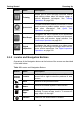
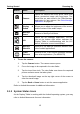
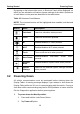
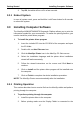
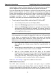
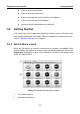
Table Of Contents
- Trademarks
- Copyright Information
- Disclaimer of Warranties and Limitation of Liabilities
- For Services and Support:
- Safety Information
- Chapter 1 Using This Manual
- Chapter 2 General Introduction
- Chapter 3 Getting Started
- Chapter 4 Diagnostics Operations
- Chapter 5 TPMS Service Operations
- Chapter 6 MaxiFix Operations
- 6.1 Navigation
- The Header
- Select Vehicle Button
- The “Select Vehicle” button on the Header allows you to specify the vehicle which you want to reference on MaxiFix, by selecting each of the vehicle attribute from a sequence of option lists. This feature helps to filter out the searches that allow on...
- 6.1.1 Terminology
- 6.2 Operations
- 6.1 Navigation
- Chapter 7 Shop Manager Operations
- Chapter 8 Data Manager Operations
- Chapter 9 Settings Operations
- Chapter 10 Update Operations
- Chapter 11 VCI Manager Operations
- Chapter 12 Support Operations
- Chapter 13 Training Operations
- Chapter 14 Remote Desk Operations
- Chapter 15 Quick Link Operations
- Chapter 16 Oscilloscope Operations
- 16.1 Safety Information
- 16.2 Glossary
- 16.3 MaxiScope Module
- 16.4 Screen Layout and Operations
- 16.4.1 Top Toolbar
- Math Channel
- A math channel is virtual channel generated by mathematical function of the input channel. It can be displayed in a scope in the same way as an input signal, and like an input signal it has its own measure axis, scaling and color. The MaxiScope module...
- Probe
- A probe is any transducer, measuring device or other accessory that you connect to an input channel of your MaxiScope module.
- Reference Waveform
- Recall Reference
- 16.4.2 Functional Buttons
- 16.4.3 Measurement Grid
- 16.4.4 Measurement Rulers
- 16.4.5 Functional Buttons
- 16.4.1 Top Toolbar
- 16.5 Troubleshooting
- 16.6 MaxiScope Firmware Update
- Chapter 17 Digital Inspection Operations
- Chapter 18 Maintenance and Service
- Chapter 19 Compliance Information
- Chapter 20 Warranty

Diagnostics Operations Getting Started
23
There is a loose connection.
There is a blown vehicle fuse.
There is a wiring fault on the vehicle or the adapter.
There is a circuit fault in the adapter.
Incorrect vehicle identification was entered.
4.2 Getting Started
Prior to first use of the Diagnostics application, make sure the VCI device has
been synchronized with the Display Tablet to establish a communication link.
See VCI Manager Operations on page 96.
4.2.1 Vehicle Menu Layout
When the VCI device is properly connected to the vehicle, and paired to the
Display Tablet, the platform is ready to start the vehicle diagnosis. Tap on the
Diagnostics application button on the MaxiSys Job Menu, the screen then
opens the Vehicle Menu.
Figure 4-1 Sample Vehicle Menu Screen
1. Top Toolbar Buttons
2. Manufacturer Buttons