
User Manual


136
box.
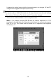
Figure 7-48 Sample Activate Channel Screen
3. Tap the left column of channel control button again to close the channel. The
closed channel button displays gray.
Channel Color
Identify each channel waveform by color.
Table 7-5 Channel Color Table
Input Channel
Color
A
Red
B
Green
C
Blue
D
Yellow
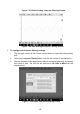
Amplitude Settings
The amplitude, probe, low-pass filtering and DLC channel settings can be configured
in the Channel control dialog box.
The amplitude settings allow you to set up the oscilloscope to capture signals with
the specified range. If the input signal exceeds the selected range, an over-range
indicator will be displayed. Select Auto to enable the device to adjust the vertical
scale automatically.