
User Manual


180
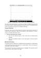
Measurement Rulers
In the coordinate grid, there are two kinds of measurement rulers, which allow the
amplitude and time duration of a waveform to be measured precisely. They are
useful when determining signal characteristics such as amplitude at specific points,
the cycle time (duration) and frequency.
The vertical Time Ruler - Tap the Ruler Activator in the bottom left corner of the
grid and drag it across the screen to the desired position. A Time Ruler is generated.
The horizontal Signal Ruler - The Signal Ruler can be generated in the similar way
by tapping the Ruler Activator in the upper right corner and dragging it downwards.
NOTE
The horizontal signal ruler varies according to the settings of the voltage, current,
frequency, duty cycle, etc.
When dragging the Measurement Rulers, a Ruler Table showing time and amplitude
values for the corresponding channels will be displayed. The Delta icon refers to the
absolute difference between the values of the rulers, which can be locked by tapping
the Lock icon. Tap the X button in the upper right corner of the ruler table to delete
all rulers.
Figure 7-10 Sample Measurement Rulers Screen
Zero Baseline
The zero baseline is marked the 0 value in the Y-axis, showing the ground level of
each channel waveform. After the channel is selected, the zero baseline can be