
User Manual


221
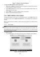
Figure 7-4 Sample OBDII CAN Bus Check Menu Screen
1. Upper Toolbar - see
Upper Toolbar on page 221 for details.
2. Main View Section – see
Main View Section and Lower Toolbar on page 221 for details.
3. Lower Toolbar– see
Main View Section and Lower Toolbar on page 225 for details.
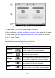
7.4.5.1 Upper Toolbar
The upper toolbar is used for configurations of various settings and operations. The
following table provides brief descriptions of each button.
Table 7-1 Upper Toolbar
Name
Button
Description
OBD Icon
Displays the device connection status. See OBD
Button
on page 222 for more information.
Start/Stop
Start or stop the device. See Start/Stop Button on
page 222 for more information.
Settings
Set the communication protocol pins manually. See
Settings Menu on page 222 for more information.
File
Print, open and save the waveform data. See File
Menu
on page 224 for more information.
Help
View the user manual and update the software.
See Help Menu on page 225 for more information.