
User Manual


89
DANGER:
To prevent injury or death, do not use the product if it appears to be damaged
in any way. Stop using the product when any abnormal operations occur.
WARNING:
Do not tamper with or disassemble the oscilloscope, connectors or
accessories. Internal damage will affect performance.
Do not block any of the instrument's air vents to avoid damage caused by
overheating.
When cleaning the oscilloscope, use wet soft cloth with mild detergent in
water. Do not allow water to enter the oscilloscope casing.
7.1.2 General Introduction
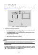
7.1.2.1 Component Locations
The input channels are located at the bottom of the VCMI device and are compatible
with many test leads and probes.
VCMI Bottom View
1. Ethernet Connector – Connects to RJ45 Network Cable
2. Vehicle Data Connector – Connects to the vehicle DLC using the provided Main
Cable.
3. Input Channel A
4. Input Channel B
5. Input Channel C
6. Input Channel D
The oscilloscope LED is located on the front panel of the VCMI device. When the
VCMI is properly connected and powered on, the oscilloscope LED flashes green
when operating in the oscilloscope mode.