Table of Contents General Notice ............................................................. 1 Introduction ................................................................ 2 Functional Description ............................................... 4 Product Troubleshooting ........................................... 7 Driver Setup ................................................................ 8 Firmware Update .......................................................10 Warranty and Service .................
General Notice The Bluetooth Diagnostic Interface has been carefully designed and tested to comply with OBDII protocols. However, some vehicle models are not in full compliance with these protocols for various reasons. In addition, the computer control systems or sensors on any given vehicle may be malfunctioning.
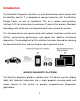
Introduction The Bluetooth Diagnostic Interface is a multi-brand device which comes with the MaxiSys tool kit. It is designed to connect wirelessly with the MaxiSys Display Tablet, as well as standalone PCs, as a vehicle communication interface (VCI) for vehicle data transmission. Thanks to the wireless Bluetooth technology, with which you are allowed to work freely around the vehicle.
Wireless Communication The Bluetooth Diagnostic Interface supports Bluetooth communication. It can transmit vehicle data to the MaxiSys Display Tablet without a physical connection. The working range of the transmitter through Bluetooth communication is about 755 feet (about 230 m). A signal lost due to moving out of range automatically restores itself when the display unit is brought closer to the VCI unit.
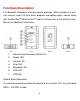
Functional Description The Bluetooth Diagnostic Interface device package, which includes the unit, user manual, and a CD with driver program and update agent, comes along TM with the MaxiSys /MaxiSys Mini TM tool kit. Please refer to the MaxiSys User Manual for additional information. 1. Vehicle Data Connector (DB15-Pin) 2. Power LED 3. Vehicle LED 4. Error LED 5. Bluetooth LED 6. USB LED 7.
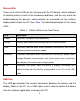
Status LEDs There are 5 status LEDs on the front panel of the VCI device, which indicates its working status as well as the hardware conditions, and are very useful for troubleshooting the device’s communication or connection to the Vehicle, display tablet and/or the PC. See Table 1 for detailed description of the status LEDs. Table 1 – Status LEDs on the Front Panel LED Description Power Illuminates solid green when powered on. Vehicle Flashes green when communicating with the vehicle’s network.
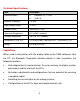
Technical Specifications Item Description Communications Bluetooth V.2.1 + EDR USB 2.0 Wireless Frequency 2.4 GHz Input Voltage Range 12 VDC Supply Current 200 mA @ 12 VDC Operating Temperature 0°C to 50°C (ambient) Storage Temperature -20°C to 70°C (ambient) Dimensions (L x W x H) 147.5 mm (5.80”) x 85.5 mm (3.37”) x 29.0 mm (1.14”) Weight 0.215 kg (0.
Product Troubleshooting This part describes problems that you may encounter while using the VCI device. Vehicle Linking Error A communication error occurs if the interface device fails to communicate with the vehicle’s control module when performing diagnostic procedures. You need to do the following check-ups: Verify that the ignition is ON. Check if the interface device’s OBD II connector is securely connected to the vehicle’s DLC. Turn the ignition off and wait for about 10 seconds.
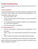
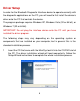
Driver Setup In order for the Bluetooth Diagnostic Interface device to operate correctly with the diagnostic applications on the PC, you will need to first install the device’s driver onto the PC that controls the device. The program package requires Windows XP, Windows Vista (32 or 64 bit), or Windows 7 (32 or 64 bit). IMPORTANT: Do not plug the interface device onto the PC until you have installed the driver program.
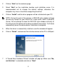
2 Click on “Next” on the welcome page. 3 Select “Next” on the installation location and installation name. It is recommended not to change the default settings; otherwise the computer may have a hard time recognizing the driver. 4 Click on “Install” and the driver program will be installed onto your PC. NOTE: During this part of the process a MS-DOS style window will pop up and may remain on your screen for a short while, which is perfectly normal.
8 Select “Install the software automatically (Recommended)”, and click on “Next”. After the progress bar finishes, click on “Finish”. Users have finished installing at this point and can run the software working with the interface device. Firmware Update Autel periodically releases updates to the device’s drivers. Updates are necessary to solve specific problems and to ensure the VCI device is working properly with the OEM software.
1 Power up the interface device and connect to the PC via the USB cable. 2 Verify the Power and USB LEDs on the front panel are illuminated. 3 Click on “All Programs” from Windows Start Menu, find the “MaxiFlash Bluetooth” entry under “Autel”, click on “UpGrade”, and wait for the program interface to pop up. 4 Select the “Update” tab and the update agent will automatically check for the available update online. 5 Press the “Next” button to install the newest firmware.
Warranty and Service Limited One Year Warranty Autel warrants to its customers that this product will be free from all defects in materials and workmanship for a period of one (1) year from the date of the original purchase, subject to the following terms and conditions: 1) 2) 3) 4) The sole responsibility of Autel under the Warranty is limited to either the repair or, at the option of Autel, replacement of the device at no charge with Proof of Purchase.