7-INCH MASTER SERIES PROMPTER ASSEMBLY AND INSTALLATION GUIDE
MSP17 Assembly and Installation Guide Autocue and QTV have been serving the broadcast industry since the mid-1950s when QTV in New York and Autocue in London supplied the very first prompters via their rental divisions. Creating broadcast history. The two companies merged in 1984 under Autocue Group and, with the introduction of the QSeries family of software, became the only company to offer the television industry a single solution for all transmission, newsroom, scripting and prompting requirements.
MSP17 Assembly and Installation Guide Contents Contents ............................................................................................. iii 1 Introduction......................................................................................... 1 1.1: 1.2: 1.3: 1.4: 2 MSP17............................................................................................................. 1 About this guide.............................................................................................
MSP17 Assembly and Installation Guide Contents 6.3: Menu options................................................................................................. 23 6.3.1: Input Select....................................................................................... 23 6.3.2: VGA Adjustments ............................................................................. 23 6.3.3: Color Adjustment .............................................................................. 23 6.3.4: Video Settings ...
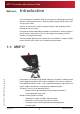
MSP17 Assembly and Installation Guide SECTION 1: Introduction For the broadcaster, production facility or event organiser requiring greater viewing distances and larger display areas, Autocue prompter display and on-camera units satisfy all your needs. Autocue on-camera units comprise prompter display, hood, mounting bracket, tripod plate and accessories.
MSP17 Assembly and Installation Guide Section 1: Introduction About this guide A variety of counterbalances and adjustable weights are available to ensure safe and stable operation and movement of mounted equipment. Where appropriate, Autocue can also provide a range of accessories, such as cue lights and remote controls, to complement your chosen system. 1.2: About this guide This document describes how to assemble and mount your chosen Autocue prompter display or on-camera unit.
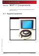
MSP17 Assembly and Installation Guide SECTION 2: MSP17 Components The following tables list the supplied and recommended components for your MSP17 on-camera unit. 2.1: Supplied equipment Item Name Illustration MSP17 Issue #: 081016 ©2003-2008 Autocue Group Ltd Power and video cable www.qtv.com 3 www.autocue.
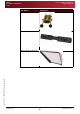
MSP17 Assembly and Installation Guide Item Name Section 2: MSP17 Components Supplied equipment Illustration Pro Plate Mounting Bracket Issue #: 081016 ©2003-2008 Autocue Group Ltd Medium Wide Angle Hood www.qtv.com 4 www.autocue.
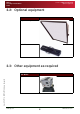
MSP17 Assembly and Installation Guide Section 2: MSP17 Components Optional equipment 2.2: Optional equipment Item Name Large Wide Angle Hood Roller Plate 2.3: Other equipment as required Item Name Issue #: 081016 ©2003-2008 Autocue Group Ltd Tripod www.qtv.com 5 www.autocue.
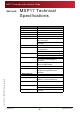
MSP17 Assembly and Installation Guide SECTION 3: MSP17 Technical Specifications ATTRIBUTE Display size Brightness Resolution Contrast Ratio Reading range Input signal Composite standard Power input Power consumption Display controls Assembly weight Monitor options Specify on purchase - Cue light Integrated card with power output to cue light and 3-pin DIN sensor connector Reduces weight by 500g (1.
MSP17 Assembly and Installation Guide SECTION 4: Assembly Procedures An Autocue On Camera Unit can be used with almost any industry-standard camera and tripod combination. On camera units comprise a tripod head attachment, prompter monitor and hood with integral two-way mirror.
MSP17 Assembly and Installation Guide Section 4: Assembly Procedures Autocue Wide Angle Bracket Wide Angle Bracket options N OTE : The vertical hood mounting bars are longer than the horizontal prompter display unit mounting bars. 4.2.1: Wide Angle Bracket options Autocue produces three wide angle bracket sets depending on the size of hood and prompter display unit that you have ordered.
MSP17 Assembly and Installation Guide Section 4: Assembly Procedures Autocue Wide Angle Bracket Bracket assembly N OTE : The illustrations below depict various sized brackets. 1. Unscrew the keyhole plates in the bracket and rotate them to the upright position. 2. Screw in the horizontal prompter display unit mounting bars. Issue #: 081016 ©2003-2008 Autocue Group Ltd 3. Screw in the vertical hood mounting bars. www.qtv.com 9 www.autocue.
MSP17 Assembly and Installation Guide Section 4: Assembly Procedures Autocue Wide Angle Bracket Adjust spacing and location of the mounting bars 4.2.3: Adjust spacing and location of the mounting bars N OTE : It is recommended that you check the spacing between the mounting bars before attaching the mounting bracket to the plate you have ordered. 1. Loosen all the mounting bars slightly so that they can freely move to the left and right. 2.
MSP17 Assembly and Installation Guide Section 4: Assembly Procedures Autocue Wide Angle Bracket Adjust spacing and location of the mounting bars 7. Align the vertical mounting bars with the screw clamps on the rear of the hood and slide the bars in. N OTE : It is recommended that you mount the hood so that it is centred along the mounting bracket. 8. Tighten the vertical mounting bars to secure them in position and remove them from the screw clamps. 9.
MSP17 Assembly and Installation Guide Section 4: Assembly Procedures Pro Plate preparation Adjust spacing and location of the mounting bars 4.3: Pro Plate preparation The Autocue Pro Plate is provided disassembled as illustrated below. The Pro Plate consists of a combined tripod slide and camera carriage, adjustable mounting rods for attaching an on-camera unit and optional pan-tilt arm. A Pro Plate can be attached to either a tripod or to a hand-held shoulder grip. 10.
MSP17 Assembly and Installation Guide Section 4: Assembly Procedures Pro Plate preparation Attach Pro Plate to a tripod 4.3.1: Attach Pro Plate to a tripod 1. Place the Pro Plate on a flat surface with the mounting slide uppermost. 2. Place the tripod camera mounting plate on to the Pro Plate mounting slide. 3. Fix the camera mounting plate in place by screwing it to the Pro Plate mounting slide.
MSP17 Assembly and Installation Guide Section 4: Assembly Procedures Attach mounting bracket to your chosen plate Attach Pro Plate to a tripod 6. When you have found the correct position on the tripod slide, secure the carriage slide in position by tightening the locking lever. 4.4: Attach mounting bracket to your chosen plate Ensure that the plate is securely attached to a tripod. N OTE : An Autocue mounting bracket is attached in the same way to a Pro, Fixed or Swing-arm plate.
MSP17 Assembly and Installation Guide Section 4: Assembly Procedures Mount prompter display unit and hood Attach MSP17 3. Tighten the locking rings to secure the mounting bracket in postion. 4.5: Mount prompter display unit and hood 4.5.1: Attach MSP17 1. Slide the horizontal rods of the Mounting Bracket into the mounting holes in the MSP17 chassis. N OTE : The prompter display unit shown is for illustration only.
MSP17 Assembly and Installation Guide Section 4: Assembly Procedures Mount prompter display unit and hood Attach Wide Angle Hood 2. Secure in the required position by tightening the locking clamp on the side of the chassis. 3. Repeat for the other clamp. 4. Ensure that the whole assembly is stable and balanced. 4.5.2: Attach Wide Angle Hood 1. Slide the locking clamps of the Wide Angle Hood over the vertical bars of the Mounting Bracket. 2.
MSP17 Assembly and Installation Guide Section 4: Assembly Procedures Mount prompter display unit and hood Attach Wide Angle Hood 3. Secure in the required position y tightening the locking clamps on the rear Issue #: 081016 ©2003-2008 Autocue Group Ltd of the hood. www.qtv.com 17 www.autocue.
MSP17 Assembly and Installation Guide SECTION 5: MSP17 Connections 5.1: Physical characteristics The prompter display unit of the Autocue MSP17 is illustrated below. Buttons Control Menu Opens the OSD menus or Opens a particular sub-menu Issue #: 081016 ©2003-2008 Autocue Group Ltd The MSP17 has four control buttons on the side of the unit. www.qtv.com 18 www.autocue.
MSP17 Assembly and Installation Guide Section 5: MSP17 Connections Physical characteristics Video and power inputs Buttons Control Exit Exits from the a sub-menu or Closes the OSD Up Move OSD cursor to highlight a sub-menu or Increase the value of a parameter Down Move OSD cursor to highlight a sub-menu or Decrease the value of a parameter The actions of the on-screen menus are described in Section 6: Prompter Operation. 5.1.
MSP17 Assembly and Installation Guide Section 5: MSP17 Connections Physical characteristics Autocue cue light 5.1.2: Autocue cue light When an on-camera unit is used, the hood can sometimes obscure the cue light on the camera. To overcome this, Autocue has developed an extension light that is attached to the hood. 1. Attach the sensor to the light on the camera. 2. Plug the sensor into the Sensor socket on the prompter display unit. 3. Attach the cue light to the top of the hood. 4.
MSP17 Assembly and Installation Guide SECTION 6: MSP17 Operation OSD (On Screen Display) menus are used to configure the prompter display unit and prepare it for displaying scripts. N OTE : While operating prompter display units, troubleshooting or maintenance tasks may need to be performed on the prompter display unit. For guidance, refer to section 1. 6.1: Connections Once your MSP17 and camera combination are securely mounted on a tripod or shoulder grip, attach the MSP17 cabling. 1.
MSP17 Assembly and Installation Guide Section 6: MSP17 Operation OSD controls Accessing the OSD controls 6.2.1: Accessing the OSD controls The Menu button on the side of the MSP17 opens the OSD controls. An example OSD menu screen is shown below.
MSP17 Assembly and Installation Guide Section 6: MSP17 Operation Menu options Input Select 6.3: Menu options 6.3.1: Input Select The first option allows you to select a video signal source for your prompter display unit. Sub-menu Options Main Picture channel VGA Component Video Scan inputs Off On PIP Mode Off Picture in Picture Side by Side 6.3.2: VGA Adjustments The following are only usable if the VGA Channel is active.
MSP17 Assembly and Installation Guide Section 6: MSP17 Operation Menu options Video Settings 6.3.4: Video Settings These settings are only selectable if a signal is present on an active video channel.
MSP17 Assembly and Installation Guide SECTION 7: Troubleshooting and Maintenance 7.1: Common problems The table below lists common problems that may occur during prompter operation. Suggested things to look for are. Problem Check... The power LED of the LCD flatpanel display is not illuminated if the power switch for the unit is in the ON position if the power cord is connected to a working power outlet.
MSP17 Assembly and Installation Guide Section 7: Troubleshooting and Maintenance Maintenance Cleaning the monitor Problem Check... Select the H-Total and Phase functions from the Position menu and change the settings to achieve a sharp and stable image (these settings may have to be repeated when you have selected another graphics mode).
MSP17 Assembly and Installation Guide Section 7: Troubleshooting and Maintenance Maintenance Care and handling advice 7.2.2: Care and handling advice • Avoid dropping the prompter display unit or any of its individual components. • Clean the monitor periodically. N OTE : Do not use abrasive cleaners or dusters when cleaning the monitor. • Do not run the prompter for excessively long periods of time. This will cause the operation of the backlight panel to deteriorate, gradually becoming dimmer.
MSP17 Assembly and Installation Guide SECTION 8: Sales and Support Information We have been working in live broadcast environments for the past 50 years and understand the importance of efficient and effective hardware and software support. We provide the latest prompting software builds for free on our website ensuring you continue to benefit from enhancements. Warranties cover all of our hardware products, with an in-house assessment and repair service offered outside of the warranty period.
MSP17 Assembly and Installation Guide Section 8: Sales and Support Information Americas enquiries QTV 306 5th Avenue Tel: +1 212 929 7755 3rd Floor Fax: +1 212 929 2105 New York e-mail: info@qtv.com 10001-3600 web: www.qtv.com USA Contacts Keith Andoos - Sales Director (Americas) Tel: +1 212 929 7755 Fax: +1 212 929 2105 Mob: +1 516 353 0113 kandoos@qtv.com Aaron Brady - Sales Manager Tel: +1 212 929 7755 Fax: +1 212 929 2105 Mob: +1 516 528 3599 e-mail: sales@qtv.
MSP17 Assembly and Installation Guide Section 8: Sales and Support Information 3. Leave a message including as much detail about the problem as practical. Email. 1. Send an email to: support@autocue.co.uk Remember to include as much detail as possible. A phrase such as “Screen blank” makes it difficult for the support staff to diagnose a problem and will delay providing you with an answer. Web site. 1. Go to www.autocue.com 2. Select "Support" and then "Problem Form" from the menu bar 3.