AutoCAD® 2008 Preview Guide www.autodesk.
AUTOCAD 2008 PREVIEW GUIDE Contents Introduction ........................................................................................................................................................ 3 Configuration...................................................................................................................................................... 3 Installing AutoCAD...........................................................................................................................
AUTOCAD 2008 PREVIEW GUIDE Introduction Make efficiency a daily part of the job with AutoCAD® 2008 software. The drafting, detailing, and conceptual design leader is showing the way once again. Meticulously refined with the drafter in mind, AutoCAD 2008 propels day-to-day drafting forward with features that increase speed and accuracy while saving time.
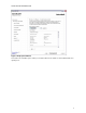
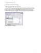
AUTOCAD 2008 PREVIEW GUIDE Figure 2. Product Installation. The Create Deployments option enables you to create pre-configured deployments for installing products on client workstations. The process for creating deployments is similar to that of installing products.
AUTOCAD 2008 PREVIEW GUIDE Figure 3. Deployment Wizard. The Install Tools and Utilities option enables you to install network license utilities as well as administrative and reporting tools.
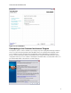
AUTOCAD 2008 PREVIEW GUIDE Figure 4. Tools and Utilities. Participating in the Customer Involvement Program As a beginner, expert, or someone in between, you can play a key role in helping Autodesk design software to meet your needs and exacting standards.
AUTOCAD 2008 PREVIEW GUIDE Figure 5. Customer Involvement Program. Specifying Hardware Acceleration AutoCAD 2008 includes support for Microsoft® Direct3D® hardware acceleration providing more flexibility for ® video cards. You can specify Direct3D or OpenGL hardware acceleration in the Manual Performance Tuning dialog box which is accessible using the 3DCONFIG command.
AUTOCAD 2008 PREVIEW GUIDE User Interface AutoCAD 2008 offers many enhancements that enable you to create a user interface that maximizes the drawing area while still providing easy access to the tools you need most! Managing Workspaces A new 2D Drafting and Annotation workspace has been added to the list of predefined workspaces.
AUTOCAD 2008 PREVIEW GUIDE example, if you adjust a visual style property on the Dashboard, the Visual Styles palette group will automatically display. Working with Palettes In AutoCAD 2008, you can easily create new tool palette tools based on existing drawing geometry even if the tool palette to which you wish to add the tool is not initially active.
AUTOCAD 2008 PREVIEW GUIDE Figure 10. Redefine drawing block with tool palette block definition When you modify the location of tools on a tool palette, their order is maintained in the tool catalog (unless the catalog file is read-only) as well as in the profile. This enables you to share your tool palettes without having to manually reorganize the tools. The new TPNAVIGATE command enables you to set a tool palette or tool palette group current using the command line interface.
AUTOCAD 2008 PREVIEW GUIDE remove them. When you select a tool in the preview pane, the corresponding tool is automatically selected in the customization tree and command list. Likewise, selecting a tool from the customization tree automatically highlights it within the preview pane and the command list. The Button Image pane displays the name of the image file below the icon preview and a tooltip displays the name of each button icon as you pass your cursor over the image. Figure 11.
AUTOCAD 2008 PREVIEW GUIDE Drawing Management AutoCAD 2008 offers new and enhanced functionality for managing the data within your drawings as well as for managing externally referenced drawing data. Working with DGN files AutoCAD 2008 enables you to attach Bentley’s MicroStation® V8 DGN files to your AutoCAD drawings and manage them as externally referenced underlays or import DGN data directly into an AutoCAD drawing. You can also export DWG™ files to V8 DGN format.
AUTOCAD 2008 PREVIEW GUIDE can choose to explode text node to text elements (this option maintains the shape of text created along a path) and you can choose to convert the DGN file to AutoCAD units using the DGN file’s Master or Sub units. Figure 13. Import DGN Settings dialog box. When you export an AutoCAD drawing to DGN file format, AutoCAD displays the Export DGN Settings dialog box.
AUTOCAD 2008 PREVIEW GUIDE Figure 14. Export DGN Settings dialog box. Working with DWF Files Beginning in AutoCAD 2007, you could attach a DWF file as an underlay in your drawing enabling you to view, measure, and snap to the vector-based data without being able to edit it. The DWF underlay functionality is enhanced in AutoCAD 2008 giving you the ability to control the visibility of layers in the DWF file.
AUTOCAD 2008 PREVIEW GUIDE Working with Xref files A new option in the XCLIP command enables you to clip the inverse of a selected boundary. For example, if you select the Invert Clip option and then specify a rectangular boundary, everything within the rectangle is removed from the display. Figure 16.
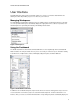
AUTOCAD 2008 PREVIEW GUIDE Managing Layers The Layer Properties Manager and the new Layer panel in the Dashboard offer many enhancements to simplify the process of creating and managing layers. You can easily rearrange the display order of layer properties by dragging and dropping the column headings and you can control which layer properties are displayed by turning them on or off from a right-click menu.
AUTOCAD 2008 PREVIEW GUIDE Figure 20. Right-click on existing layer. You can display objects differently in selected layout viewports while retaining their original layer properties in model space and in other layout viewports. With layer property overrides, you no longer need to use tedious and error-prone methods such as duplicating geometry on separate layers or making copies of xrefs.
AUTOCAD 2008 PREVIEW GUIDE BYLAYER using the new SETBYLAYER command. The SETBYLAYER command enables you to modify multiple properties at the same time and it works on objects within blocks and nested blocks as well as the block definitions themselves. A new SetByLayer Settings dialog box, accessible from the SETBYLAYER command, enables you to control which properties to include in the operation. Figure 22.
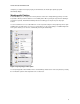
AUTOCAD 2008 PREVIEW GUIDE A Settings button in the Layer Properties Manager provides access to the new Layer Settings dialog box where you can enable layer evaluation, apply the layer filter to the layer toolbar, and change the background color for viewport overrides. Figure 24. Layer Settings dialog box. The first time you Save or Plot a drawing, AutoCAD 2008 creates a list of reconciled layers based on the existing layer names.
AUTOCAD 2008 PREVIEW GUIDE Figure 25. Unreconciled Layer Notification. The Layer Properties Manager automatically creates a layer filter for unreconciled layers. You can review the list of unreconciled layers and then manually select and reconcile layers using the Reconcile option from the right-click menu. Figure 26. Unreconciled Layers. The new Layer Panel on the Dashboard acts as a central location for your Layer tools. It includes all of the tools from the Layers toolbar and more! Figure 27.
AUTOCAD 2008 PREVIEW GUIDE Figure 28. Faded locked layers. Managing Layouts and Sheets AutoCAD 2008 offers many enhancements that make it easier for you to work with drawing layouts and sheets. In-place editing enables you to rename a layout by double-clicking on the layout tab and you can drag and drop layouts to reorder them. Use familiar tools (Ctrl and Shift) to select multiple layouts then and drag them to their new location.
AUTOCAD 2008 PREVIEW GUIDE Figure 30. Import layouts from a drawing into the current sheet set. A new option in the right-click menu of the Sheet List tab enables you to publish your sheet set in reverse order. When this option is enabled, the sheets that you plot using Publish to Plotter or Publish using Page Setup Override will plot in reverse of how they are listed in the sheet set manager. Figure 31. Publish in Reverse Order.
AUTOCAD 2008 PREVIEW GUIDE Drawing Annotation Annotation is a crucial part of your design drawings and creating annotations can consume a considerable amount of your workday. Fortunately, new and improved functionality in AutoCAD 2008 enables you to annotate your drawings with greater flexibility and efficiency than ever before.
AUTOCAD 2008 PREVIEW GUIDE Figure 32. Annotative toggles. Objects that are created using the Command Line Interface, including Text, Dimensions, Tolerance, Leaders, and Multiple Leaders, can be modified after creation to enable the Annotative property. You can use the Properties window to change the Annotative property of any existing annotative-type object.
AUTOCAD 2008 PREVIEW GUIDE In addition to applying the annotative property on a per-object basis, you can create annotative styles. The Annotative option has been added to the Text Style, Dimension Style, and Multileader Style dialog boxes. If the Annotative option is enabled for a style, that style name will be preceded by an Annotative icon helping you identify which styles are annotative when viewing them in a style list.
AUTOCAD 2008 PREVIEW GUIDE Figure 35. Annotative Scales. AutoCAD automatically creates a representation of the annotative object for each of the specified scales. When you select the object, you can see the multiple scale representations. If you prefer not to see all the supported scale representations when the objects is selected, you can use the SELECTIONANNODISPLAY to display only the current representation.
AUTOCAD 2008 PREVIEW GUIDE Figure 37. Scale List. When you specify an Annotation Scale, the corresponding Viewport Scale is automatically applied and the annotative objects for the selected scale are displayed using their appropriate scale representations. Any annotative objects that do not contain a scale representation for the specified annotation scale are not displayed.
AUTOCAD 2008 PREVIEW GUIDE Figure 39. Annotation Scaling panel on the Dashboard. Annotative scaling is not available in earlier releases of AutoCAD. However, an option in the Open and Save tab of the Options dialog box enables you to maintain the visual fidelity of your annotative objects when saving to earlier file formats. When you save an AutoCAD 2008 drawing with this option selected, each scale representation of every annotative object is saved as a normal (non-annotative) object on its own layer.
AUTOCAD 2008 PREVIEW GUIDE Using Multiple Leaders New Multiple Leader tools enable you to create leaders with more control and flexibility than ever before. You can easily access the Multiple Leader tools from the new Multileader panel on the Dashboard. Figure 41. Multileader Panel on the Dashboard. Using the Multiple Leader tool (MLEADER command) you can create a leader head first, tail first, or content first.
AUTOCAD 2008 PREVIEW GUIDE Figure 43. MultiLeader Style Manager. Overrides for some of the multiple leader properties are available from the Options selection when creating a multiple leader. And you can use the Properties window to modify properties of existing multiple leaders.
AUTOCAD 2008 PREVIEW GUIDE Using the Multileader Collect tool (MLEADERCOLLECT command), you can combine multiple block–type multiple leaders into a single multiple leader with multiple blocks. Figure 46. Collected Multiple Leaders. Working with Text The MTEXT Editor has been updated in AutoCAD 2008; providing more flexibility and control over your text.
AUTOCAD 2008 PREVIEW GUIDE Figure 49. Column controls. A new Paragraph dialog box enables you to specify tabs and indents as well as paragraph alignment and spacing. Figure 50. Paragraph dialog box. Spell checking has been enhanced in AutoCAD 2008 to further automate the spell checking process. When you launch the spell checker, the Check Spelling dialog box is immediately displayed without first requiring you to select objects.
AUTOCAD 2008 PREVIEW GUIDE Figure 51. Check Spelling dialog box. A new Check Spelling Settings dialog box provides more control over the spell checker behavior. You can specify whether to check dimension text, block attributes, and external references. Furthermore, a list of exclusion options enables you to specify sets of words that should be ignored such as words with numbers or punctuation. Figure 52. Check Spelling Settings dialog box.
AUTOCAD 2008 PREVIEW GUIDE Block attributes have been updated to support multiple lines of text. The Attribute Definition and Edit Attribute dialog boxes include a new Multiple Lines control. When you select Multiple Lines, the Default text box is disabled and you’re provided with access the Multiline Attribute editor. Figure 53. Multiline Lines option in the Attribute Definition dialog box.
AUTOCAD 2008 PREVIEW GUIDE Creating Dimensions AutoCAD 2008 offers new and enhanced dimensioning functionality, which includes automatic alignment options, dimension breaks, jogged dimensions, text placement, and tolerances. The new Dimension panel on the Dashboard provides easy access to the many dimensioning tools. Figure 55. Dimension Panel on the Dashboard.
AUTOCAD 2008 PREVIEW GUIDE Figure 57. Inspection Dimension dialog box. You can add a jog to linear dimensions to represent measurements whose values are not the same length as the dimension line. Jogged dimension lines are typically used when a sheet is too small to display the true length of a dimension line. Using the Dimension Jog tool (DIMJOGLINE command), you can select the dimension and indicate where you want to place the jog.
AUTOCAD 2008 PREVIEW GUIDE Figure 59. Dimension Spacing Enhancements to diametric, radial, and jogged radial dimensions enable you to dimension an arc beyond its endpoints. The process for creating these dimensions hasn’t changed. However, when you specify the location of the dimension line, you can drag beyond the endpoints of the arc. AutoCAD will automatically create an arc extension line using the same properties, such as extension line color and extension line offset, as traditional extension lines.
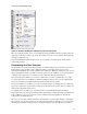
AUTOCAD 2008 PREVIEW GUIDE Figure 62. Dimension Tolerance Alignment Working with Table Data AutoCAD 2008 offers significant new and enhanced functionality to help you maximize the value of your drawing data by defining and applying table styles, extracting drawing data to tables, and integrating drawing data with external data files such as Excel® spreadsheets.
AUTOCAD 2008 PREVIEW GUIDE Figure 63. Insert Table dialog box. The first option, Start from empty table, was the default method in previous releases of AutoCAD. It enables you to create an AutoCAD table by manually entering static table data. Alternatively, if you already have data in an Excel spreadsheet, you can copy and paste the Excel data as AutoCAD entities (PASTESPEC command). Pasting Excel data as AutoCAD entities automatically creates a new table with the static values already entered.
AUTOCAD 2008 PREVIEW GUIDE Figure 65. Excel data links. You can edit, rename, delete and preview existing data links using the Data Link Manager. When you create a new data link or edit an existing one, an expandable dialog box enables you to customize the data link settings. For example, you might specify that the cell contents from the AutoCAD table can be written back to the source file. Figure 66. Modify Excel Data Link.
AUTOCAD 2008 PREVIEW GUIDE Figure 67. Data link notification bubble. The linked cells in the AutoCAD table are locked to prevent editing from within AutoCAD and the range of linked cells is indicated by green corner brackets. If you select a linked cell, its status is indicated by the locked and linked icons as well as by information in the tool tip. Figure 68. Linked Table Cells.
AUTOCAD 2008 PREVIEW GUIDE For example, if you use lines and arcs to represent the gas, drainage, and water lines on a subdivision layout, you might want to extract the length property of all the lines and arcs on the Gas, Drainage, and Water layers. Figure 70. Object Data Extraction. Depending on the type of data you extract and how you wish to use it, you may choose to export the data to an Excel spreadsheet for further calculations.
AUTOCAD 2008 PREVIEW GUIDE You can add even more functionality to the data extraction table by inserting formula columns and total footers to perform calculations on the table data. You can access these by right-clicking over the column headers while on the Refine Data page of the Data Extraction Wizard. Figure 71. Formula Columns. Regardless of what method you use to create an AutoCAD table, you will want to take advantage of custom table styles.
AUTOCAD 2008 PREVIEW GUIDE You can adjust a long table, regardless of how it was created, to fit on a drawing sheet by automatically wrapping it across multiple rows. Simply select the table and then adjust it using grips or the new Table break tools in the Properties window. Figure 73. Table Wrapping.
AUTOCAD 2008 PREVIEW GUIDE Visualization Managing Materials The Materials palette has been updated to provide faster, easier access to materials properties. It includes expandable panels, which enable you to view and edit material setting without having to access multiple dialog boxes. Figure 74. Materials palette. In the Material Editor panel, you can specify the type of material and select from a wide range of pre-defined templates.
AUTOCAD 2008 PREVIEW GUIDE Figure 75. Material Editor Panel. The Maps panel enables you apply diffuse, opacity, and bump maps to a material and you can synchronize any or all of the maps with the material. When the maps are synchronized with the material, any changes you make to the material will automatically apply to the specified maps, saving you time and reducing errors.
AUTOCAD 2008 PREVIEW GUIDE The Advanced Lighting Override panel enables you to adjust material lighting parameters for greater realism. Adjustable overrides include Color Bleed, Indirect Bump, Reflectance, and Transmittance Figure 77. Advanced Lighting Overrides. The Material Offset and Preview panel enables you to preview the material as well as adjust the offset and rotation values. Figure 78. Material Offset and Preview panel.
AUTOCAD 2008 PREVIEW GUIDE Figure 79. Photometric Properties. In addition to the improvements to materials and lighting, a new –RENDER command (don’t forget the dash “-“) enables you to use the command line interface to select from the available render presets. With this command line option, you can automate the rendering process by creating a script to batch render multiple scenes.