
Technical data

Creating a Production Drawing
31
Inserting Centerlines Automatically
Creating centerlines on your drawing views is simple with Autodesk
Inventor. To generate centerlines automatically for the front view:
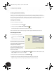
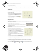
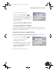
1. Move your cursor into the front view (lower-left view on your sheet),
right-click, and then select Automated Centerlines.
The Centerline Settings dialog box appears, allowing you to define
situations where centerlines should automatically be generated.
2. In the Centerlines Settings dialog box, select the Cylindrical
Features option, and both Projection options, Axis Normal
and Axis Parallel .
3. Click OK to close the dialog box and create the centerlines using
these settings.
Saving Your Production Drawing of the Part
To save your production drawing of the clamp top part:
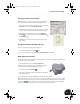
1. On the Standard toolbar, click the Save tool.
2. In the Save As dialog box, ensure the file name is Clamp_top.idw and click Save.
Making Revisions to the Part
Even though you have been working on the drawing of the part, the 3D model is still open in another window.
To continue working on the 3D model:
• From the Window menu, choose Clamp_complete.iam.
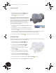
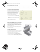
Although the model may appear complete, it still has sharp edges.
You can remove these sharp edges using the Chamfer tool.
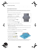
1. On the Panel bar, click the Chamfer tool.
2. Select the four semicircular edges of the halfshell (on lower left and
upper right of the part).
3. In the Chamfer dialog box, type 0.5 mm for the distance, and then click OK.
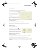
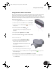
Tip: Even though you cannot see one inner edge on the upper right of the part, you can select it by selecting
through the model. Also, if you hover the cursor over an element on the model for a few seconds, a multiple
selection tool appears. Use the arrows to cycle through the options until the element is highlighted,
and then click the rectangular button in the center of the tool to accept that selection.
INV8_TD_Book5.book Page 31 Tuesday, October 28, 2003 10:51 AM