
Technical data

Working with Multiple Parts in an Assembly
40
Loft features require at least two sketches or boundaries. Your
first sketch on this part will be based on the bottom face of the
lower halfshell.
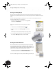
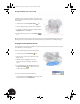
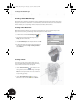
1. On the Panel bar, click the Project Geometry tool.
2. Select the elliptical edge on the bottom face of Clamp_A.
3. To quit the Project Geometry tool, in the graphics window,
right-click and then choose Done.
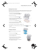
4. To finish sketching, you can also click the Return
tool.
Tip: The Return tool returns you to the previous state. In this case, you will exit 2D sketching and return to part
modeling. If you are in part modeling mode and click the Return tool, you will return to assembly modeling.
Creating the Lower Sketch for the Loft
A second sketch is required for the loft feature. To position another sketch, you first need to create a work plane
that is offset from your existing sketch.
To create an offset work plane from the existing sketch:
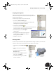
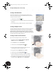
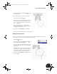
1. On the Panel bar, click the Work Plane tool.
2. Move the cursor over the lower elliptical face of the
Clamp_A:1 part.
3. When the surface is highlighted in red and a
rectangular boundary is displayed, drag the face
down.
4. In the Offset dialog box, type 45-15.5 and then click
the green check mark to accept the value and
create the offset work plane.
To create a new sketch on this offset work plane:
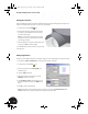
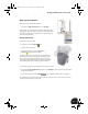
• In the graphics window, right-click one of the edges of the
work plane and then choose New Sketch.
INV8_TD_Book5.book Page 40 Tuesday, October 28, 2003 10:51 AM