
Technical data

Creating a Sheet Metal Design
47
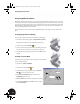
Creating a Sheet Metal Part from the Sketch
Now, you create a sheet metal part using the open sketch.
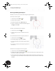
1. On the Panel bar, click the title and select Sheet
Metal Features.
Note: If you do not see this menu option, perhaps
you did not select the template Sheet Metal.ipt as
described earlier. In this case, activate it from the
Applications menu by selecting Sheet Metal.
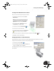
2. In the graphics window, right-click and choose
Isometric View (or simply press F6).
3. On the Panel bar, click the Contour Flange tool.
4. Select the open contour as the profile.
5. In the Contour Flange dialog box, click the Centered
option and then type a distance of 55 mm.
6. If the preview of the part is not offset to the outside of the sketch, click the Offset button.
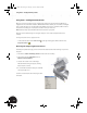
7. Click OK to create the sheet metal part.
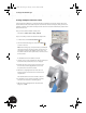
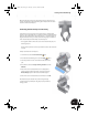
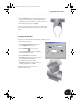
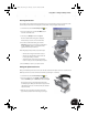
Changing the Thickness of Sheet Metal Parts
The default thickness of the sheet metal part is a bit thin. With Autodesk Inventor software, you can easily
change the sheet metal thickness and other crucial parameters globally.
1. On the Panel bar, click the Styles tool.
2. In the Sheet Metal Styles dialog box, type 1.5 mm for the
thickness, click Save, and then click Done.
Your default settings have now been changed, and the sheet metal
part is updated.
INV8_TD_Book5.book Page 47 Tuesday, October 28, 2003 10:51 AM