
Technical data

Creating a Sheet Metal Design
49
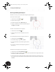
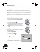
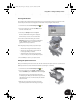
After performing these steps, the sheet metal part moves into the proper
location and the lower cutout of the Clamp_B part adapts to the size of the
outer face of the sheet metal part.
Positioning Parts Accurately in an Assembly
In the previous section you saw how to orient parts in an assembly with
respect to one another. Each time you create an assembly constraint between
parts, you reduce the ability of a part to freely move — commonly known as
degrees of freedom. Next, you visually check remaining degrees of freedom
on the sheet metal part and then fully constrain that part.
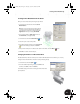
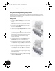
• In the graphics window, move the cursor over the sheet metal part, and
then drag the part.
Notice how the part does not move up and down or side to side, but is free
to rotate.
To fully constrain the sheet metal part:
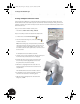
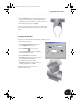
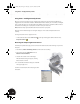
1. On the Panel bar, click the Place Constraint tool.
2. In the Place Constraint dialog box, select the Angle option.
3. Select the planar face on the outer left tab of the sheet metal
part.
4. In the Browser, under the Origin of Clamp_welded:1, click the
XZ Plane.
5. If the arrows on the selected surfaces are not displayed in a
direction similar to the image shown on the right, select the
Directed Angle option in the Place Constraint dialog box.
6. If the arrows on the selected surfaces are similar, then click OK.
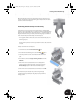
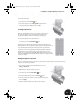
The sheet metal part is rotated into position using the Angle
constraint. Now, if you attempt to drag the part, the part will not
change position.
INV8_TD_Book5.book Page 49 Tuesday, October 28, 2003 10:51 AM