
Technical data

Designing Welded Assemblies
51
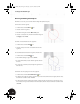
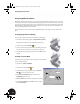
7. With the Arrow Side 1 selection button highlighted, select
the edge where the previously created chamfers meet (the
highlighted selection should display a completely closed loop).
8. In the Weld Feature dialog box, click Apply.
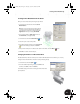
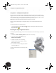
The cosmetic weld is displayed on the model as an orange line with
the weld symbol displayed to the side showing the weld seam type
and size.
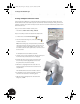
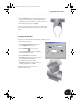
Creating a 3D Fillet Weld
Next, you create a 3D fillet weld between the Clamp_B and Clamp_C parts.
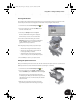
In the Weld Feature dialog box:
1. Click the Arrow Side Symbol button and then
select a Fillet Weld type (see arrow 1).
2. Click the Fillet Weld type (see arrow 2).
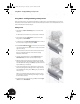
3. Click the Arrow Side tab and then type 1 mm for
the depth and 1 mm for the size.
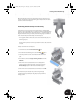
4. Click the General tab, and then with the
Arrow Side 1 button selected, select the outer
face of the sheet metal part Clamp_C.
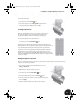
5. In the Weld Feature dialog box, click the
Arrow Side 2 button, select the outer face of
the Clamp_B part, and then click OK.
The 3D fillet weld seam is created along the
intersection of the two parts.
2
1
INV8_TD_Book5.book Page 51 Tuesday, October 28, 2003 10:51 AM