OPERATORS MANUAL & SPARE PARTS LIST TURF TROOPER 3
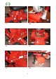
K A E B 1 4 H C L 2 5 I D H J G F 3 6 1
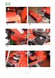
L M 7 10 J G 8 11 G R 9 12 2
T P 13 16 Q O 14 17 C 15 18 3
19 21 T 20 22 4
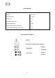
CONTENTS Page CERTIFICATE OF CONFORMITY SPECIFICATIONS INTRODUCTION SAFETY INSTRUCTIONS ASSEMBLING THE MACHINE OPERATING THE MACHINE SAFETY INTERLOCK SWITCHES TO START THE ENGINE TO STOP THE ENGINE STEERING WORKING INSTRUCTIONS SPEED CONTROL CYLINDER DRIVE CLUTCH CUTTING WITH THE MACHINE THROTTLE CONTROL BRAKE & PARKING BRAKE LIFTING & LOWERING MOWER UNITS FRONT CYLINDERS REAR CYLINDER MAINTENANCE LUBRICATION ENGINE LUBRICATION MACHINE LUBRICATION BATTERY TYRES ADJUSTMENTS STEERING LINKAGE DRIVE TRAIN ADJU
EC DECLARATION OF CONFORMITY I, the undersigned, of Allen Power Equipment Ltd., The Broadway, Didcot, Oxon OX11 8ES, certify that the machine described below: Category Make Type Model Cutter Lawnmower ALLEN Ride-on Turf Trooper III 60” (1530mm) Cylinder Comply with the following Directives.
SPECIFICATIONS MODEL ENGINE GXV 270 MANUFACTURER Honda POWER HP 8.5 MAX PERMISSIBLE (KW) 6.4 ENGINE SPEED (RPM) 3600 SOUND POWER LEVEL (LWA) dB(A) 99 SOUND PRESSURE LEVEL (LPA) dB(A) 86.
INTRODUCTION SAFETY INSTRUCTIONS The ALLEN TURF TROOPER 3 is an advanced ride-on cylinder mower designed to cut grass quickly, efficiently and economically, giving your lawn the velvet finish only a quality cylinder mower can deliver. Please ensure that the instructions contained in this manual are read carefully and fully understood by any person likely to operate the Trooper.
The seat is fitted with a safety cut-out switch which stops the engine as soon as the operator dismounts unless certain parameters are met. Should this happen, the ignition switch must also be turned off to prevent the battery discharging. ASSEMBLING THE MACHINE Always wear stout shoes and suitable clothing. Fit the front cylinders noting that they are “handed”. These are fitted with the cylinder lift arms in the raised position.
WORKING INSTRUCTIONS With the engine running at full speed, the machine may be used in either travelling or cutting mode. If travelling, ensure that all the SAFETY INTERLOCK SWITCHES The machine is fitted with a number of interlock switches to give additional safety to the customer. Here are some tips relating to the use of the switches:- cylinders are lifted and latched ‘K’, Fig. 1 and ‘L’, Fig. 5 into the travelling position and that the Cylinder Drive (lever) ‘G’, Fig. 6 is disengaged.
THROTTLE CONTROL CUTTING WITH THE MACHINE The Throttle Control ‘I’, Fig 6 is a combined choke and engine speed control housed in one unit. The lever should be placed in the relevant position for the function required. The Trooper is designed to have all three cylinders operating at the same time. There is no method of disconnecting separate cylinders, therefore all cylinders must be lowered from the transport position on to the grass.
Use Castrol L.M. grease or equivalent. If working on lifted parts ensure that adequate support is provided. Occasionally lubricate all other moving parts by oil can, in particular the Throttle Control at the lever and engine ends, cylinder unit latches, neutral adjustment plungers, exposed screw threads on mower adjustments etc. Do not alter engine speed above the maximum quoted in the engine specification. Before making any adjustment or clearing a blockage, STOP the engine.
If belt replacement is necessary, remove the main access panel as detailed above ‘R’. Then remove the Locating Spigot Bar from the fan/pulley assembly, Fig. 15 and separate the fan/pulley assembly, Fig. 15 and the coupling, Fig. 2. The Belt ‘O’ can be replaced easily. CYLINDER CLUTCH ADJUSTMENT Lay the belt into its pulley and the engine pulley. Refit the Fan/Pulley assembly and Locating Spigot Bar allowing the rubber coupling to align with the coupler halves.
necessary. Removal of the Cylinder Belt greatly eases this operation. GUARANTEE If there is any component, or components, manufactured by ALLEN POWER EQUIPMENT LTD that is found to be defective within 12 months from the date of purchase (or in the case of a machine used for hire purposes, 45 days). ALLEN POWER EQUIPMENT LTD undertake to replace the faulty component/components free of charge through authorised dealers.
! !" ! " "
# ! $ % & ! % ' '! ( % ! % ' ! # # ! $ ! $
" ! " " !" ! " ( " ' ! " "
'
! ! ! " " ! ! !" ! " ! " ( ( ! " " ) ! ( " " ! " " * '! # ! " $
CUTTING CYLINDER ASSEMBLIES ITEM No. 1 2 3 4 5 6 7 8 9 10 11 12 13 14 15 16 17 18 19 20 21 22 23 24 25 26 27 28 29 30 31 32 33 34 35 36 PART No.
( # # !" ( $ $ # # # # ' $ $ $ $ * * ! " + # ' $ # $
! ( " ( ! " " ( ( ( !
! " " # ! , -../01.23.-0./0 , -../01.2/-0.4 , -../01.2/5675/-8./05-.20 ! '( ! ! % $ % 9 -../01.
autoguide equipment Heddington, Nr Calne, Wiltshire, SN11 0PS Telephone: +44 (0) 1380 850885 Fax: +44 (0) 1380 850010