
Installation Instructions

Title:
Installation Specifications and User Manual, Radar
Sensor, 24 GHz
Doc. No. E E814702
INSTALLATION SPECIFICATION Rev. 000, Page 13 of 16
6.0 24 GHZ SENSOR SYSTEM
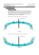
The following observations refer to the combination of several 24 GHz Sensors into
one sensor system. Many applications require several sensors networked together to
achieve the desired function. The sensors should be placed in the best possible
location for optimal coverage and range performance relative to the specific
applications. The optimal locations will be highly dependent on the desired
applications and the bumper dimensions. Autoliv can perform analysis and
characterization to determine sensor locations to best achieve a desired performance.
Attention should be paid that the installation specifications for individual sensors from
chapter 5 are maintained. Due to the various installation situations and applications, a
measurement check is required to verify the actual installation implementation.
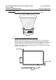
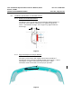
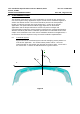
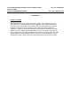
6.1. Coordinate System
Figure 8 shows the coordinate system used for identifying sensor position in a
multi-sensor application. The arrows indicate positive values. The most
forward location on the bumper was selected as reference point. The Z-axis is
the vertical axis. Z-values are indicated from the ground surface.
Figure 8
Y
Z
ϕ
ϕϕ
ϕ
X