® Model 425 Installation Guide ® © 2001 Directed Electronics, Inc. Vista, CA N425A 3-01 Rev. E 1.
table of contents What Is Included . . . . . . . . . . . . . . . . . . . . . 3 Installation Points to Remember . . . . . . . . . . 4 Tools Required . . . . . . . . . . . . . . . . . . . . . . . 4 Deciding on Component Locations . . . . . . . . . Siren . . . . . . . . . . . . . . . . . . . . . . . . . . Control Module . . . . . . . . . . . . . . . . . . . . Valet®/Program Switch . . . . . . . . . . . . . . . . Status LED . . . . . . . . . . . . . . . . . . . . . . Optional Starter Kill Relay . . . . . . . .
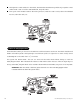
what is included ■ The control module (see diagram) ■ Two 476A remote transmitters ■ A Stinger® Doubleguard® shock sensor on-board the control module ■ A Revenger® Soft Chirp® siren ■ The plug-in status LED ■ The plug-in Valet®/program switch ■ Primary harness ■ Door lock harness Primary Harness Port Shock Sensor Adjustment Door Lock Harness Port 2-Pin Micro LED Port 4-Pin Optional Sensor Port © 2001 Directed Electronics, Inc.
installation points to remember This product represents many years of research and development. It is a sophisticated product that should be installed by experienced security installers only. Please do not attempt installation of this product without reading this guide. The system has been designed to provide the ultimate in security, coupled with limitless convenience and expansion options.
deciding on component locations locations for the siren Some things to remember when mounting the siren: ■ Keep it away from heat sources. Radiators, exhaust manifolds, turbochargers, and heat shields are all things to avoid. ■ Mount it where a thief cannot easily disconnect it, whether the hood is open or shut. Both the siren and its wires should be difficult to find. This usually involves disguising the wire to look like a factory harness. ■ We recommend against grounding the siren to its mounting screws.
■ The higher the control module is in the vehicle, the better the transmitter range will be. If you put the control module under a seat or inside a metal dashboard, range will suffer. ■ Some good control module locations: Above the glove box, inside the center console, above the underdash fuse box, above the radio, etc. locations for valet/program switch Ensure that the location you choose for the switch has sufficient clearance to the rear. The switch should be well hidden.
locations for the status LED Things to remember when positioning the Status LED: ■ It should be visible from both sides and the rear of the vehicle, if possible. ■ It needs at least 1/2-inch clearance to the rear. ■ It is easiest to use a small removable panel, such as a switch blank or a dash bezel. Remove it before drilling your 9/32-inch hole. ■ Use quick-disconnects near the LED wires if the panel is removable. This allows mechanics or other installers to remove the panel without cutting the wires.
finding the wires you need Now that you have decided where each component will be located, you’re going to find the wires in the car that the security system will be connected to. IMPORTANT! Do not use a 12V test light to find these wires! All testing described in this manual should be performed using a digital multimeter. obtaining constant 12V We recommend two possible sources for 12V constant: The (+) terminal of the battery, or the constant power supply to the ignition switch.
4. Turn the ignition key switch to the run position. If your meter reads (+)12V, go to the next step. If it doesn’t, probe a different wire. 5. Now turn the key to the start position. The meter display should remain steady, not dropping by more than a few tenths of a volt. If it drops close to or all the way to zero, go back to step 3. If it remains steady at (+)12V, you have located an ignition wire. finding a (+) parking light wire The (+) parking light wire is often found near the switch.
How to find a door pin switch trigger wire with your multimeter: 1. Set to DCV or DC voltage (12V or 20V is fine). 2. In most cars, fasten the (+) probe of your meter to (+)12V constant. 3. Probe the wire you suspect of being the door trigger wire. If the meter reads (+)12V when any door is opened, you have found a trigger wire. NOTE: Make sure the wire you use “detects” all the doors! Some newer GM vehicles lack standardtype pin switches.
making your connections When connecting the security system’s wires to the wires in the vehicle it is important that the connections are tight and no bare wire is exposed. In this section, two types of connections are described that may be used to connect the wires from the security system into the vehicle’s wiring. Both types of connections are electrically acceptable if made correctly. Other types of "tap-in" connections, such as T-Taps are not acceptable. solderless butt connections 1.
solder connections 1. Using your wire strippers and razor knife, strip approximately 1/2-inch of insulation off the wire to be connected to, without cutting the wire. Stripped Vehicle Wire 2. Twist the security module’s wire around the bare section of the vehicle’s wire. Vehicle Wire Module Wire 3. Solder the bare connection thoroughly using rosin core solder. Vehicle Wire Module Wire 4. Completely insulate the connection with electrical tape. 12 © 2001 Directed Electronics, Inc.
primary harness (H1), 12-pin connector primary harness wiring diagram H1/1 H1/2 H1/3 H1/4 H1/5 H1/6 H1/7 H1/8 ______ ______ ______ ______ ______ ______ ______ ______ ORANGE WHITE WHITE/BLUE BLACK/WHITE GREEN BLUE (-) 500 mA ARMED OUTPUT (-) 200 mA LIGHT FLASH OUTPUT (-) 200 mA CHANNEL 3 SELECTABLE OUTPUT (-) 200 mA HORN HONK OUTPUT (-) DOOR TRIGGER INPUT, ZONE 3 (-) INSTANT TRIGGER INPUT, ZONE 1 VIOLET (+) DOOR TRIGGER INPUT, ZONE 3 BLACK (-) CHASSIS GROUND INPUT H1/9 ______ YELLOW (+) SWITCHED IG
NOTE: If connecting the orange wire to control another module, such as a 529T or 530T window module, a 1 amp diode (type 1N4004) will be required (see following diagram). H1/2 WHITE (-) parking light output This wire provides a (-) 200 mA output to flash the parking lights. This is suitable for driving (-) light control wires in Toyota, Lexus, BMW, some Mitsubishi, some Mazda, etc. If the vehicle has a positive parking light circuit a relay must be used to flash the parking lights.
■ A latched/reset with ignition output functions similarly to the latched output, but will also reset (output will stop) when the ignition is turned on then off. ■ A 30-second timed output will send a signal for 30 seconds when channel three is pressed. This output can also be programmed to provide a second unlock pulse when the disarm button is pressed within 15 seconds after disarming the system. This can be used to unlock the passenger doors when installing progressive door locks.
H1/6 BLUE (-) instant trigger, zone 1 This input will respond to a negative input with an instant trigger. It is ideal for hood and trunk pins and will report on Zone 1. It can also be used with 506T Glass Breakage Sensor, as well as other DEI® single stage sensors. The H1/6 BLUE instant trigger wire can be used to shunt sensors during operation, using the auxiliary channels. When any of the auxiliary channels are transmitted, the H1/6 BLUE wire monitors for a ground.
H1/8 BLACK (-) chassis ground connection Remove any paint and connect this wire to bare metal, preferably with a factory bolt rather than your own screw. (Screws tend to either strip or loosen with time.) We recommend grounding all your components, including the siren, to the same point in the vehicle. H1/9 YELLOW (+) ignition input, zone 5 Connect this input to the (+)12V ignition wire. This wire must show (+)12V with the key in Run position and during cranking.
H1/11 RED (+) 12V constant power input Before connecting this wire, remove the supplied fuse. Connect to the positive battery terminal or the constant 12V supply to the ignition switch. NOTE: Always use a fuse within 12 inches of the point that you obtain (+)12V. Do not use the 15A fuse in the harness for this purpose. This fuse protects the module itself. H1/12 RED/WHITE (-) 200 mA channel 2 output When the system receives the code controlling channel 2 for longer than 1.
door lock harness (H2) wire connection guide type A: (+) 12V pulses from the switch to the factory relays The system can control a Type A system directly, with no additional parts. The switch will have three wires on it, and one will test (+)12V constantly. The others will alternately pulse (+)12V when the switch is pressed to the lock or unlock position.
type B: (-) pulses from the switch to the factory relays This system is common in many Toyota, Nissan, Honda, and Saturn models, as well as Fords with the keylessentry system (some other Fords also use Type B). The switch will have three wires on it, and one wire will test ground all the time. One wire will pulse (-) when the switch locks the doors, and the other wire will pulse (-) when the switch unlocks the doors. This type of system is difficult to mistake for any other type.
(-) CHASSIS GROUND (+) 12V LOCK UNLOCK MASTER SWITCH (+) 12V CONSTANT FUSED CUT X H 2/A GREEN (-) LOCK WIRE 87 87A 85 (+) 12V CONSTANT FUSED X X CUT X MOTOR (+) LOCK WIRE MOTOR (+) LOCK WIRE 86 30 (+) 12V CONSTANT FUSED H 2/C BLUE (-) UNLOCK WIRE 87 87A 85 86 30 (+) 12V CONSTANT FUSED type D: after-market actuators In order for this system to control one or more aftermarket actuators, a 451M or two relays (optional) are needed.
type E: mercedes-benz and audi (1985 & newer) Type E door locks are controlled by an electrically activated vacuum pump. Some Mercedes and Audi models use a Type D system. Test by locking doors from the passenger key cylinder. If all the doors lock, the vehicle's door lock system can be controlled with just two relays (optional). The control wire can be found in either kick panel and will show (+)12V when doors are unlocked and (-) ground when doors are locked. To interface, see the diagram below.
type G: positive multiplex This system is most commonly found in Ford, Mazda, Chrysler and GM vehicles. The door lock switch or door key cylinder may contain either one or two resistors. When interfacing with this type of door lock system, two relays or a DEI 451M must be used. (See diagram below.) single-resistor type If one resistor is used in the door lock switch/key cylinder, the wire will pulse (+)12V in one direction and less than (+)12V when operated in the opposite direction.
type H: negative multiplex The system is most commonly found in Ford, Mazda, Chrysler and GM vehicles. The door lock switch or door key cylinder may contain either one or two resistors. When interfacing with this type of door lock system, two relays or a DEI 451M must be used. (See diagram below.) single-resistor type If one resistor is used in the door lock switch/key cylinder, the wire will pulse ground in one direction and resistance to ground when operated in the opposite direction.
on-board doubleguard shock sensor There is a Doubleguard® shock sensor inside the control unit. Adjustments are made via the rotary control as indicated above. Since the shock sensor does not work well when mounted firmly to metal, we recommend against screwing down the control module. The full trigger of the on-board shock sensor reports zone 2. (See Table of Zones section of this guide.
plug-in harnesses super-bright LED, 2-pin white plug The super bright LED operates at 2V DC. Make sure the LED wires are not shorted to ground as the LED will be damaged. The LED fits into a 9/32-inch mounting hole. Be sure to check for clearance prior to drilling the mounting hole. valet/program switch, 2-pin blue plug The Valet®/program switch should be accessible from the driver’s seat. It plugs into the blue port on the side of the control unit.
BLUE, GREEN wires The blue and green wires are multiplex inputs. They are both tied to the same zone. If an input of less than 0.8 seconds is supplied to either wire the Warn Away response will occur. An input longer than 0.8 seconds to either wire will initiate the triggered sequence and report zone 4. system features learn routine The System Features Learn Routine dictates how the unit operates. It is possible to access and change any of the feature settings using the Valet®/program switch.
NOTE: The Valet® pulse count feature (10) and the channel three timed output (11) have five possible settings each. Pressing the disarm (or channel 2) button will toggle through all the possible settings. 5. Release the Valet®/program switch. once a feature is programmed ■ Other features can be programmed. ■ The Learn Routine can be exited if programming is complete.
system features menu FEATURE NUMBER ONE-CHIRP SETTING TWO-CHIRP SETTING 1 Active arming Passive Arming 2 Audible arm/disarm confirmation on Audible arm/disarm confirmation off 3 Ignition-controlled locking on Ignition-controlled locking off 4 Ignition-controlled unlocking on Ignition-controlled unlocking off 5 Active locking Passive locking 6 0.8 second door lock pulses 3.
4 IGNITION-CONTROLLED UNLOCKING ON/OFF: When turned on, the vehicle doors will unlock when the ignition is turned off. 5 ACTIVE/PASSIVE LOCKING: If passive arming is selected in Feature 1, then the system can be programmed to either lock the doors when passive arming occurs, or only lock the doors when the system is armed via the transmitter. Active locking means the system will not lock the doors when it passively arms. Passive locking means that the system will lock the doors when it passively arms.
transmitter/receiver learn routine The system comes with two transmitters that have been taught to the receiver. The receiver can store up to four different transmitter codes in memory. Use the following learn routine to add transmitters to the system or to change button assignments if desired. The transmitter learn routine can be locked using the optional PC interface or DEI® Bitwriter™. If the learn routine is locked no transmitters can be programmed to the system. 1. Open a door.
Channel 2: If any transmitter button from a known transmitter is programmed to channel two, all transmitters will be erased from memory, and system features will return to factory default settings. This is useful in cases where the one of the customer’s transmitters is lost or stolen. This will erase any lost or stolen transmitters from the system’s memory. It can also be used to start from scratch if the transmitter buttons were programmed incorrectly.
long-term event history The system stores the last two full triggers in memory. These are not erasable. Each time the unit detects a full trigger, the older of the two triggers in memory will be replaced by the new trigger. To access long-term event history: 1. Turn on the ignition. 2. Press and hold the Valet®/program switch. The LED will flash in groups indicating the last two zones that triggered the unit. NOTE: The Warn Away® triggers are not stored to memory.
■ Door input does not respond with the progressive trigger, but with immediate full alarm: Which zone does the LED indicate? If the LED indicates that the impact sensor caused the trigger, the sensor may be detecting the door opening. Reducing the sensitivity or relocating the sensor can often solve this problem. (See Table of Zones section of this guide.) ■ The Valet® switch does not work: Is it plugged into the correct socket? (See Plug-In Harnesses section of this guide.
notes © 2001 Directed Electronics, Inc.
Wiring Quick Reference Guide 36 © 2001 Directed Electronics, Inc.