
Installation guide


26 © 2001 Directed Electronics, Inc. Vista, CA
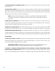
plug-in harnesses
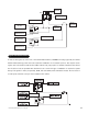
The super bright LED operates at 2V DC. Make sure the LED wires are not shorted to ground as the LED will be damaged.
The LED fits into a
9
/32-inch mounting hole. Be sure to check for clearance prior to drilling the mounting hole.
The Valet
®
/program switch should be accessible from the driver’s seat. It plugs into the blue port on the side of
the control unit. Since the system features Valet
®
by remote, the switch can be well hidden. Consider how the
switch will be used before choosing a mounting location. Check for rear clearance before drilling a
9
/32-inch hole
and mounting the switch. The GRAY wire in the two-pin plug may also be used as a (+) Ghost Switch
™
input and
can be connected to any (+) switch in the vehicle (see Feature Descriptions section of this guide).
NOTE: Please note for the customer the location of the Valet
®
/program switch in the section pro-
vided in the Owner’s Guide.
The black three-pin port can be used for programming the unit or to accommodate a serial controller. When using
the optional DEI Bitwriter
™
or PC Interface module (DEI part number 996T) for programming, it is possible to con-
figure any or all of the programmable functions using an IBM-compatible personal computer. When using a serial
controller, such as DEI’s 103T Keypad or the DEI 400A Car★Com, basic operating functions can be controlled
without the use of a remote transmitter. For more information please refer to the guides packaged with these DEI
compatible products.
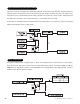
four-pin optional sensor harness
The red wire supplies constant power to the optional sensor.
The black wire supplies ground to the optional sensor.
BLACK wire
RED wire
data input port, 3-pin black port
valet/program switch, 2-pin blue plug
super-bright LED, 2-pin white plug